This is a collection of tips and techniques submitted by UAMF members over the years.
As there is such a large amount of information here, everything has been broken down into sub-categories.
This section of the FAQ is currently a work - in - progress.
I guess that everyone knows how to make a cone out of plastic card (or paper).
However, it's not quite as easy to make a truncated nose cone, if, for example, you've managed to do something nasty to your Millenium Falcon cockpit exterior and/or your Millenium Falcon cockpit transparency.
So, here is one way to do it:
First step is to work out what the critical dimensions are (or will be). These are :-
1. The diameter of the back of the cone (about 39mm for the MF)
2. The diameter of the front of the cone (about 20mm for the MF)
3. The length of the side between the front and the back of the cone (25mm for the MF)
On a piece of paper, draw a line equal to the perimeter of the larger circle (3.1415926 x the diameter).
At a distance equal to the length of the side (measurement 3, above), draw a parallel line, equal to the perimeter of the smaller circle, with the centre of the line at the centreline of the longer line (clear as mud?).
Draw a line from the edge of the longer line, to the edge of the shorter line, from each side. They should intersect at the centreline. This point is now the centre.
Place a compass (ie a drawing compass!) at the centre, and extend it to the longer line. Draw an arc tangential to the longer line.
Do the same for the shorter line.
The length of the arcs should be at least the length of the perimeter of each circle. The length of an arc is the radius x the angle (in radians). As most of us work in degrees, you can convert degrees to radians by multiplying the angle in degrees by pi (3.1415926) and dividing by 180. 1 radian = about 57 degrees.
For a truncated cone similar to the Millenium Falcon, 10thou card is an appropriate thickness to transcribe the curves to, and it is malleable enough to cut and curl around. It can be joined with either liquid poly or superglue.
Making Card Buildings
Repairing Raised Panel Lines
Nose Weighting
Often you will find that the kit instructions tell you to put noseweight into a kit to prevent it from "tail-sitting".
You can use many forms of noseweight, some of the most popular are:
You could also use tungsten putty. This is available from fishing tackle shops, is denser than lead and has the advantage of being very easily pressed into place.
There is also a product from Deluxe Materials called "Liquid Gravity". This is basically very fine lead shot that is poured into place and then secured with liquid superglue.
If you use coins, some approximate weights for UK coinage are:
Whatever you use, remember that it is torque that matters -so the further you can position your weight from the model's balance point, the more effective it will be.
Some models don't have sufficient room in the nose for the amount of noseweight that you will need - Canberras for example - and so you will need to put weights into other places too.
Behind cockpits, beneath cockpit floors, even the fronts of engine nacelles and the noses of drop tanks are all places that you might be able to place weights.
Rigging Basics
You can use different grades of fishing line, which also comes in different colours, or fine elastic thread which you can buy from a haberdashery shop, (it's used to make things like socks have elastication). However, the Aeroclub thread has just the right amount of elasticity to allow you to make your rigging appear tight, but reamians flexible enough to give a little when you're manipulating it. (Available from Aeroclub)
Having got your bits, grab your first biplane kit.
Study the rigging on a good picture of the plane beforehand to determine where the rigging goes.
Use a very fine drill bit in a pin vice to drill tiny holes at the anchor points, through which the line can be threaded, using glue to cement it in place.
Pick your first "anchor point" and dot some superglue in it, with a cocktail stick.
Dab the end of a piece of thread with Zipkicker, using your other cocktail stick.
Put your thread tip on the anchor point and Bingo! It's set.
Put a blob of superglue on your next anchor point.
Put Zipkicker on your thread.
Stretch the thread over the anchor point, so that it comes into contact with the superglue. Again, it will set.
For thicker rigging, two or more threads can be twisted together.
The thread can also be painted, (which makes it look thicker), or coloured with black marker pen or gel pen.
Here are couple of useful sites;
http://www.wwi-models.org/misc/rigging.html
http://www.ww1.org.uk/rigging.htm
Making Mirrors
Here are a few ideas from the forum to make realistic mirrors:
Some kits, such as Revell's 1/48 F-86D, come with the mirrors in the form of transparent parts.
A piece of chrome Bare Metal foil can be applied to the back of these, and then the mirror can be painted as normal for a very realistic effect.
Holographic effect confetti cam also be used to good effect as HUD projector lenses.
Rescribing Panels
Rescribing can be a time consuming chore, and sometimes your model looks worse at the end of it than it did before you started.
So tedious and fraught with danger can the job be that often people choose not to bother. Whilst that seems a good option at the time, many an otherwise good model has been spoilt by dissappearing panel lines, or a smooth surface where on the real machine a mass of lines are a distinctive feature. In fact, it's a job that can be as simple as you choose to make it, and the simpler you make things, the less likely you are to make mistakes.
Allegedly.
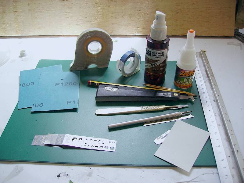
Let's gather our tools and potions.
Depending upon what you want to do, you may not need everything that I have there.
These are my essentials for rescribing: a metal rule, Tamiya and Dymo tape, gap filling superglue and accelerator, a few cocktail sticks, some good quality fresh wet and dry paper in 800 and 1200 grits, a scrap of 10 thou plastic card, a sharp HB pencil and finally a selection of tools with which to do the actual scribing. There I have a Tamiya scriber, my bog standard scalpel with a No.11 blade, an engineers' scribe with a replaceable tip, and a couple of etched stainless steel saw blades.
Each has its use in different situations, although for the majority of work I tend to choose the engineers' scribe.
You will no doubt find whichever implement you are most comfortable with and gravitate towards that in much the same way.
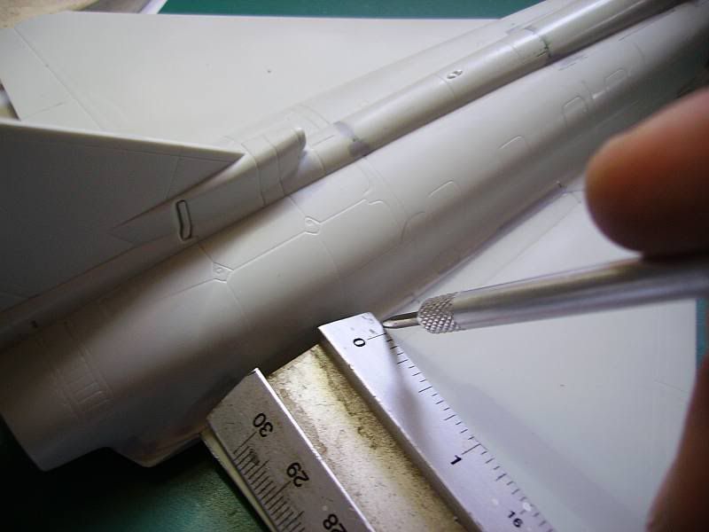
The simplest of all things to rescribe is a straight line. For this you just need your scribing tool of choice and an edge to guide it. It's important that the guide doesn't move whilst you're working, to keep it in place you could use a spot of blu-tak under a ruler, forgo the ruler and use Dymo tape, paint the back of a length of plastic card with Copydex (grippy stuff, that) or simply rely upon your vice-like grip.
Once you've secured the guide in place, you need to scribe the line. Hold the tool at angle of between 45 and 60 degrees, and draw it along the guide in one direction only.
Don't be tempted to go back and forth, as the action of the tool against the plastic can raise microscopic burrs in the line. If you go over these t'other way, the tool can bounce out of the cut and make a stray mark. The other thing to watch out for is pressure. You need to apply about the same amount of pressure as you would writing on a pad with a ballpoint pen so as not to leave an impression on the underlying page. This is also good opsec for budding secret agents.
You may need to run the tool along the line two or three times to achieve the depth you want.
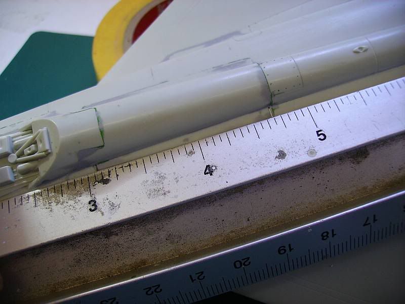
Obviously you need to keep an eye on where the line starts and finishes, but sometimes the edge of your ruler will obscure things to the extent that you can't tell just by looking.
The easy way out is to simply mark the ends of the line with your pencil.

Now when you lay the rule on the model, you can see the marks you made which will keep you on the right track.
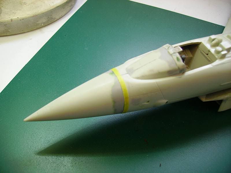
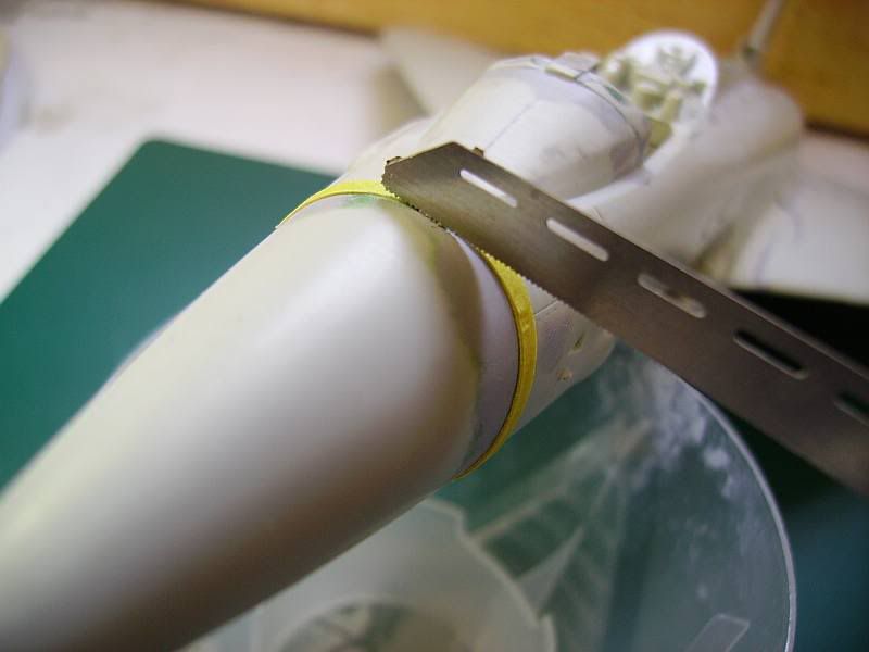
That's straight lines taken care of. What about the tricky ones, like radial lines that run around the circumference of a fuselage, for instance?
Obviously your ruler won't be much good here, and your Dymo tape is similarly useless as it wont conform to compound curves.
The way I like to do these is by using Tamiya tape. First I cut it into strips about 1.5 - 2mm wide, and then attach one end firmly to the start point of my line.
Keeping the tape under tension, it is possible to run it carefully around your line. Because it's been cut into thin strips, compound curves are rarely a problem.
Usually I like to build up two layers.
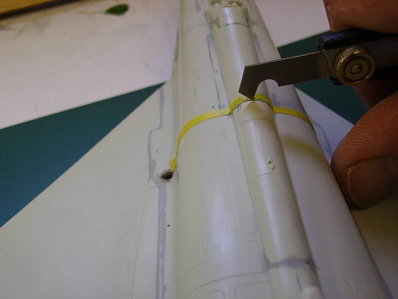
Once you have your guide in place, you need a suitable tool to do the scribing with. My preference is one of the Airwaves etched saw blades, as they can be laid on the model against the guide and drawn gently around the model to cut the line. It's important not to use a saw blade that has any set on its teeth unless you want your rescribe job to like Matchbox's mad trench digger has been at work.
Keep at it gently, using just enough pressure on the blade to get the lightest of cuts, but at the same time sufficient to keep the blade from wandering, until you're all the way around. Once you have a line all the way around, you can go back over it to get the depth you need. This is much easier than the initial scribe, as the first cut will guide the blade as long as you keep the pressure right.
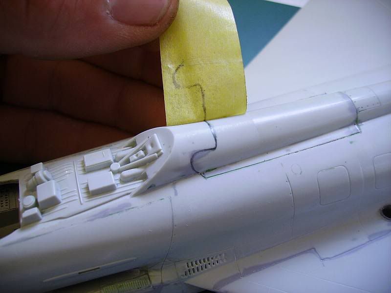
Now that we're all confident and raring to go with the tricky stuff, we might as well do the real stinkers. Here's one on Revell's Typhoon, at the forward edge of the airbrake. Sorry for the blurry picture, my camera decided that the starboard leading edge was far more interesting.

I've gone over the line in pencil carefully, ready for the science bit. Take some Tamiya tape, and burnish it down over the area you're interested in.
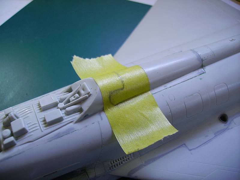
The trick part is when you lift the tape off carefully...
And there's your line already transferred to the sticky side of the tape. Carefully put that onto a scrap of thin plastic card.
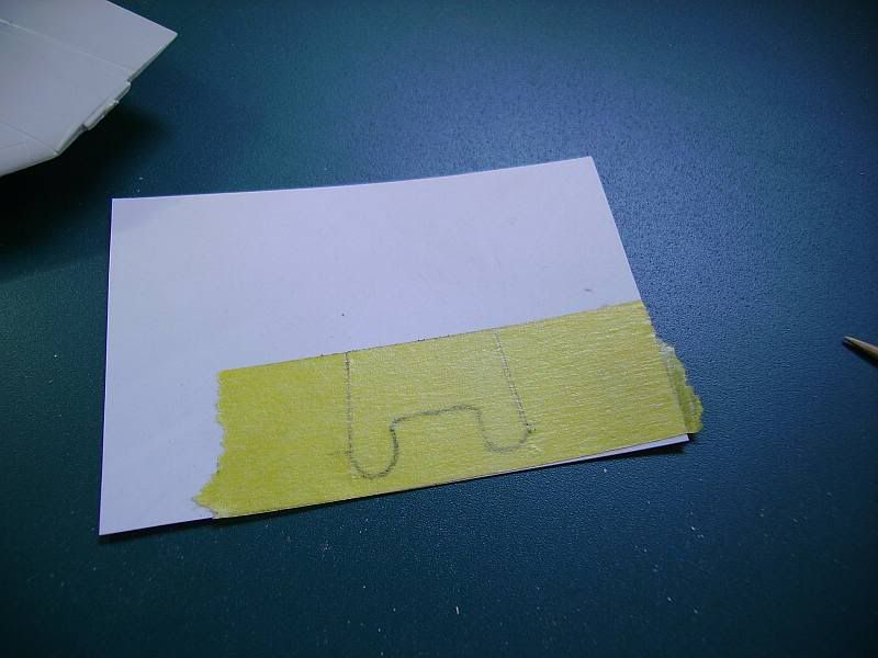
Now you can cut out a template from the card using your piece of tape as a pattern. Sand the edges until you're happy with it.
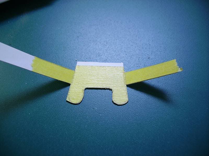
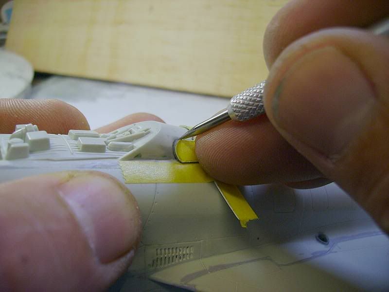
I've left a little tabs on there to stick it down to the model with. Just lay your shiny new template onto the model, tack it down with some tape and we're good to go.

For these awkward jobs I find the engineers' scribe the most useful tool. Nothing else can turn into the tight corners as well. Keep the template pressed against the model and scribe away.
All that's needed now, as with all rescribed lines, is to polish off the burrs with the wet and dry.
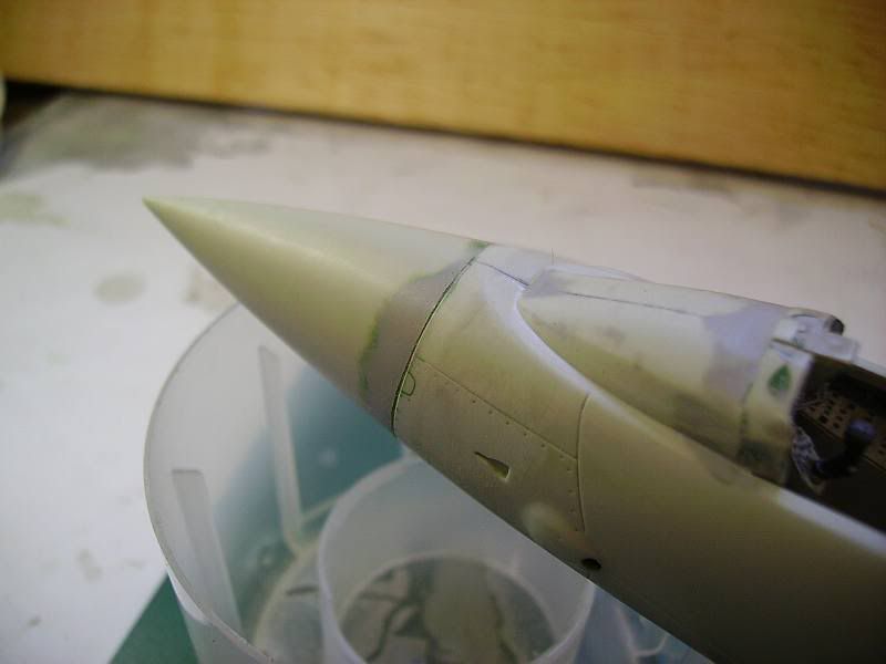
Part three: when panel lines attack, or what to do when it all goes badly wrong.
Here you can see a small circular panel that I made a mess of.
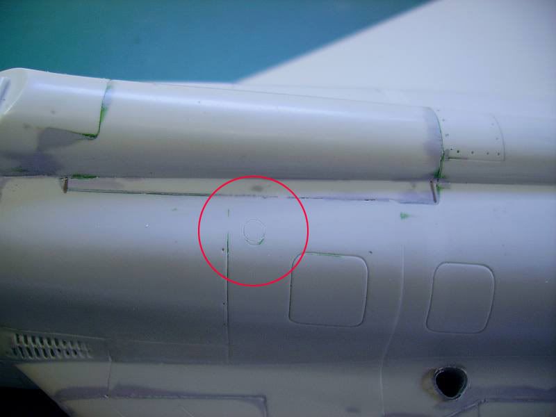
That was down to thinking that the existing line was deep enough to guide my scriber to do the job freehand. Duh. Facepalm. Best put it right before doing it again, properly.
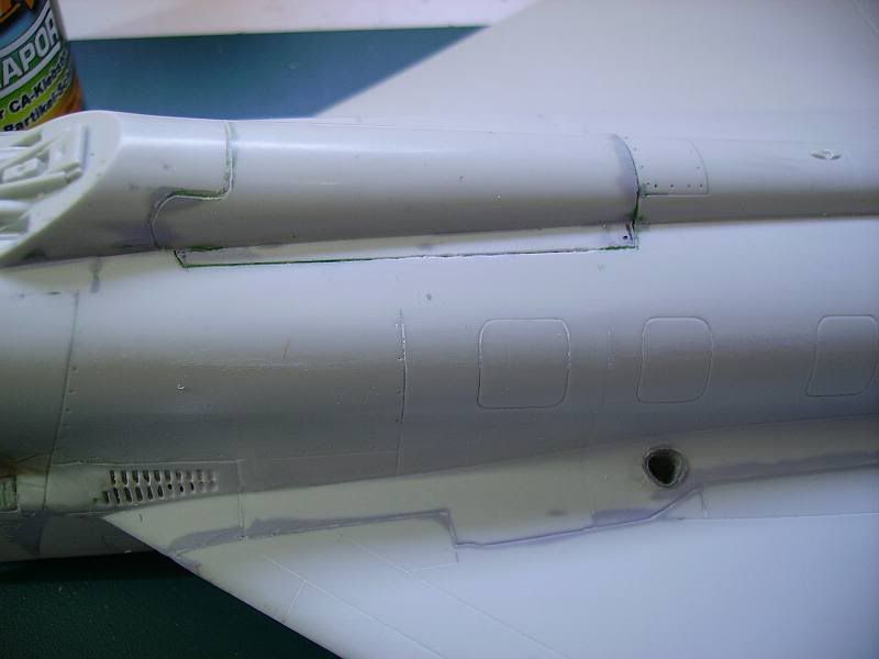
I'll use some superglue on the tip of a cocktail stick to fill the bad line.

A quick blast of accelerator, and it can be sanded back and polished out. Nobody need ever know. Divvint say owt.
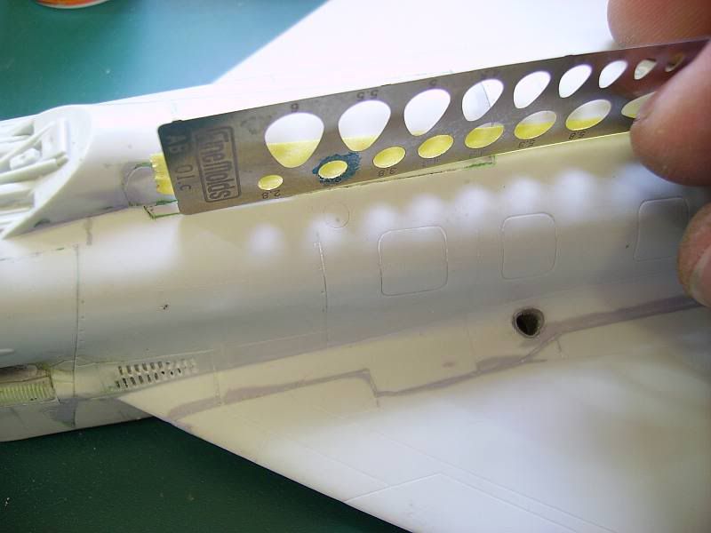
To do it properly, I'll use a scribing template. These come in all shapes and sizes, from simple generic shapes such as squares and circles to complex hinge patterns. If a model-specific one is too pricey, try to find a metal drafting template which will cover most of your needs.
First thing to do is to tape it down along just one edge, and then hold it down firmly onto the surface of the model to do the scribing.
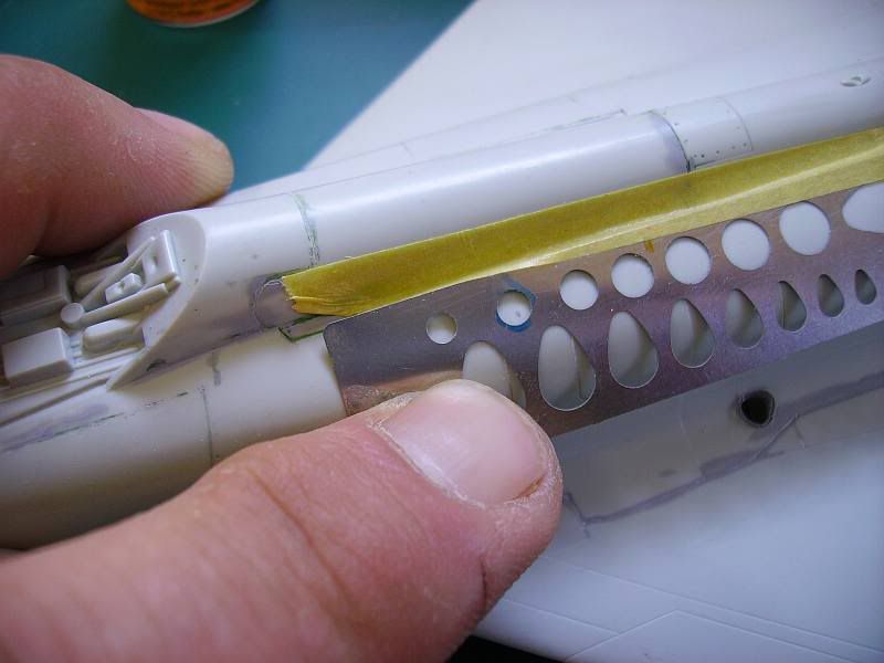
Carefully lift it up to see how it went. If you need to go deeper, your tape "hinge" will let you drop it back in the same place to another go.
As a last step, some people like to run liquid cement such as Tamiya Extra Thin or lacquer thinner into the newly scribed lines to smooth them out.
Making half of something
Recently, I lost half a carburettor intake.
Initially, I couldn't be bothered to try and scratchbuild a replacement, although I did try, starting off with a spare fuel tank.
Then I decided, after some gentle encouragement that my model looked wrong without the intake, to try a different approach.
Basically, whilst many of us are incapable of making a nice, symmetrical object, such as a circle, or oval, we are capable of doing half a one. Also, many of us are able to copy half of something, but not the full item. This is due to our handedness, be it left- or right-handedness.
(As an aside, an apprentice artist or sculptor could pass the grade once they had drawn or made a perfect sphere. If they failed in this task, they had top start again, until they got it right. From this, we get the phrase "it's all gone pear-shaped").
So, first step was to affix my surviving half to a suitably sized piece of plastic. In this case, I used two pieces of thick plasticard, glued together;

From this chunk of plastic, a corresponding half of a carburettor intake will emerge.
Keeping it simple, one step at a time, I filed away the plastic in one plane only, (side view);


Next, I filed down the next plane, (plan view), taking care not to overdo it;


Next came the tricky part...using sandpaper, I carefully removed the sharp corners between the vertical and horizontal edge;


The front of the intake has quite a complex shape to it;

Using the same principle as before, I got so far;


That gave me the basic shape and I was able to drill out the front of my piece, using a minidrill, a small, sharp knife and a needle file;

Dry-fitting the piece to the underside of the models nose, it didn't quite fit.
Spot the difference between the original half and my half;

That's right...and once I'd removed most of that surplus plastic from the inside, it fitted rather well;

Stretching Sprue
This is one of those oft-quoted techniques, used by many modellers and is an art, rather than just a simple technique anyone can do well.
Essentially, it involves placing a length of surplus plastic, usually a piece of sprue, over a heat source and pulling it apart to form a fine thread...or pitot...or rigging wire...or raised detail...etc..
Not all plastics are suitable, but most, if not all, kit plastic seems to do the job well enough.
The jury is out on what is the best plastic to use, from which manufacturer, but harder plastic seems to work better and coloured plastic seems better than your average uncoloured grey. Clear plastic, similar to that used in kit transparencies, seems to be the best of all, but this is usually in short supply.
You need to create a length of plastic, ideally trimmed of any tabs and sticky-out bits.
Your sprue should contain a few good lengths of what you'll need.
Heat sources need to be small, accessible and controllable.
Obviously, using a flame has all sorts of potential risks associated with it, so be careful. (Here endeth the H&SE Lecture).
It's easier to apply the plastic to the heat and not the other way round, so a stable heat source is recommended.
People use candles, particularly those little squat tea light candles. I tend to use the gas ring on low.
The method;
Stretching spue to get the right length of the right thickness of thread/pitot/aerial/wire takes practice. Fortunately, you'll have plenty of sprue to practice with. Initially, you'll end up with tapering pieces, with thicker ends, getting thinner in the middle. I find this great for making pitot tubes for noses. It's harder, but possible with practice, to pull your plastic apart so that you get a length of consistent thickness. Some have discovered that you can stretch plastic tubing. The tubing remains, but gets thinner as you stretch it out. This is great for making guns or exhausts, for example.
Quick cockpit detailing
Like many modelers, especially of the classic kits, I don't like detailing cockpits.
I'm also not especially concerned about whether my cockpits are accurate or detailed enough to withstand close scrutiny.
My 1/72 models are intended to look nice from several inches away. However, in many older kits the cockpit detail was so sparse that building it straight OOB would embarrass even me;
something has to be done before closing up the fuselage, even if the canopy is to be left closed, just to give anyone who might peer through that thick canopy glazing for a moment something to look at.
The trick is to not get so wrapped up in detailing the cockpit that it adds days (or weeks!) and reduces are enjoyment of the build.
A good goal is to get the cockpit of your typical simple kit detailed and the fuselage closed up within an hour of opening the kit box; at any rate, to complete it in a single working session.
I have put together a few techniqes that allow me to do this, with practice, in under 60 minutes on the average WWII-era single seat fighter that makes up the bulk of my modeling.
I thought some of the techniques might be of interest.
I call this process pseudo-detailing because I generally do it without consulting references, unless I am able to pull something up quickly on the web.
The same techniques could be used to do real detailing; it would just be a matter of cutting and painting everything in the proper shapes and sizes rather than just proper-LOOKING shapes and sizes.
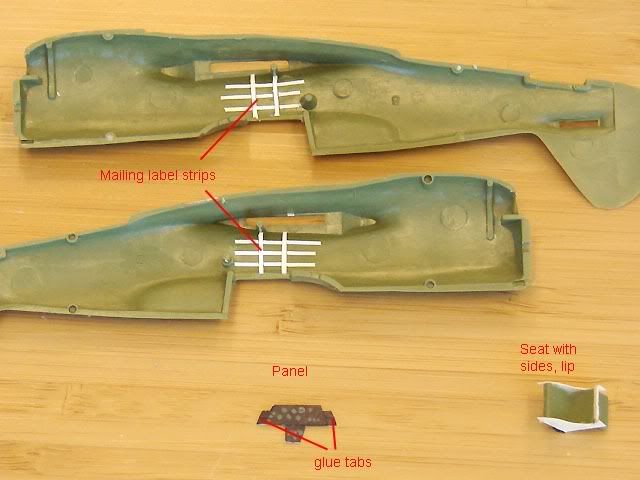
For purposes
of this demo I assume you are building a typical 1/72 WWII-era single-seat fighter from a kit designed 30 or 40 years ago whose cockpit detail consists of a bench-type seat and maybe an instrument panel and floor if you are lucky.
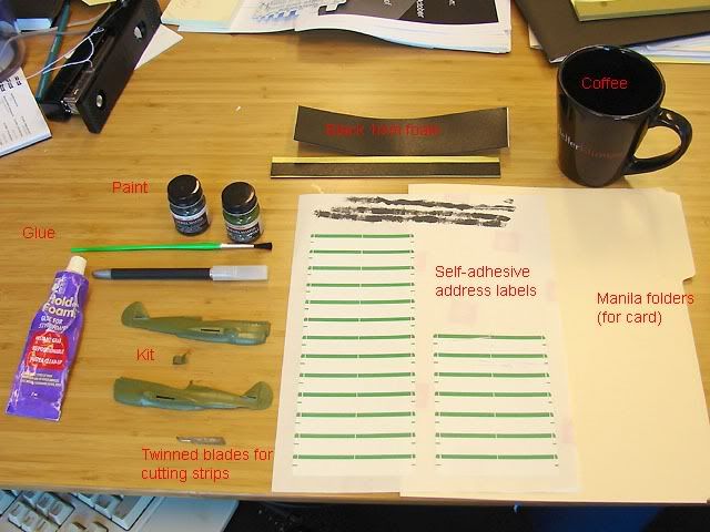
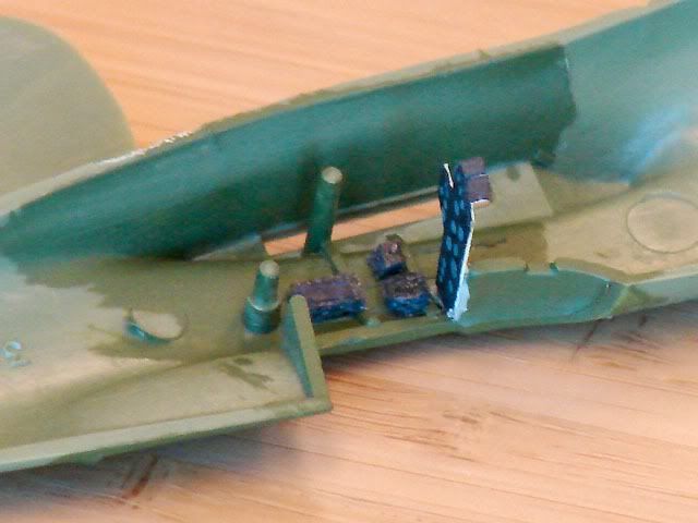
The kit that I will be detailing for this demo is the Airfix 1/72 P-40E, which has only a bench seat. If your kit has more detail than this, obviously you can skip some steps.
The main trick repeated in the steps below is to minimize the use of glues and cements that have to set by using materials that are self-adhesive where possible, and reducing the use of paints that have to dry by using things that are already the right color or coloring things in a way that dries instantly (e.g. Sharpie pen). Anyway, here is:
August's 60-Minute Cockpit Pseudo-Detail Recipe
First, gather the following materials:
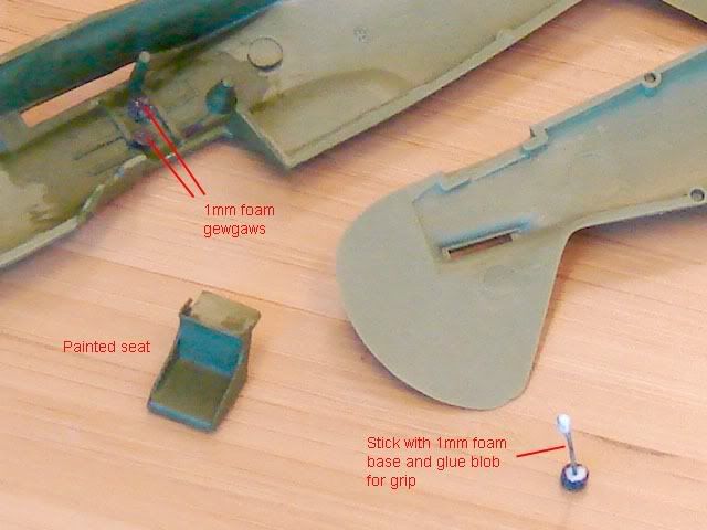
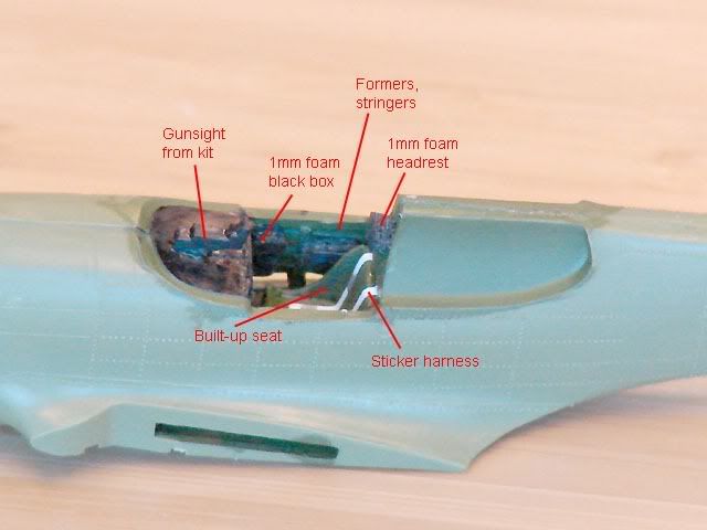
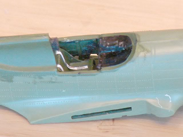
Sequence of assembly & painting
Removing Tape Glue
Hiding gaps with tape
Filling gaps with plasticard


Stripping chrome from plastic
Making mass balances
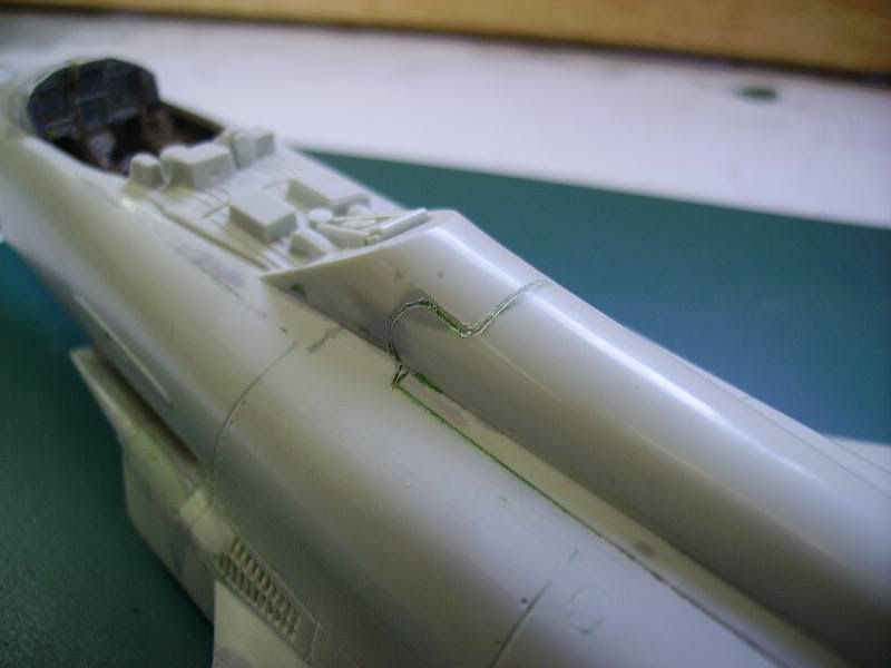
Strengthening weak joints
Copying a part with resin and plasticine
For one off parts, a two part mould for resin casting can be made using plasticine rather than the more usual RTV silicone.
The key (no pun intended) is to have some Lego handy.
The mould, all closed up, but with resin inside, ready to remove:

The moment of truth ...

A bit of filler would fix this up;

What do you think?

Rough cast iron effect
Clingfilm light covers
You can use food wrap/cling film/glad wrap to create landing light covers such as the ones seen on the leading edge of Beaufighters.
You need:
Cling film/glad wrap.
Klear/Future
1. Cut out a small square of cling film just larger than the landing light you what to cover, say a millimetre extra every side.
2 . Brush some Klear/future around the edges of the landing light

3. Before the Klear dries, place the cling film over the landing light hole. And brush some more Klear over the cling film and its edges.

4. If you don't like the little bit of shine form the Klear, coat the edges of the light cover with a dull coat.

Its the same process as applying decals with Klear, but using cling film/food wrap.