Evening All,
Thanks gentlemen for the kind remarks - I greatly appreciate them.
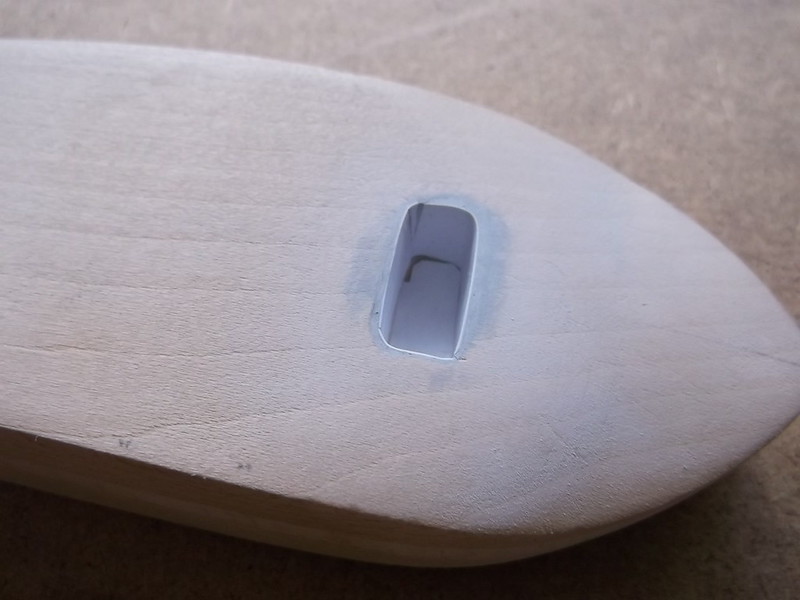
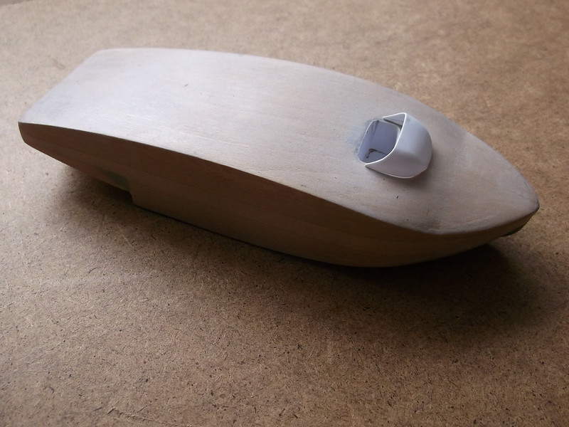
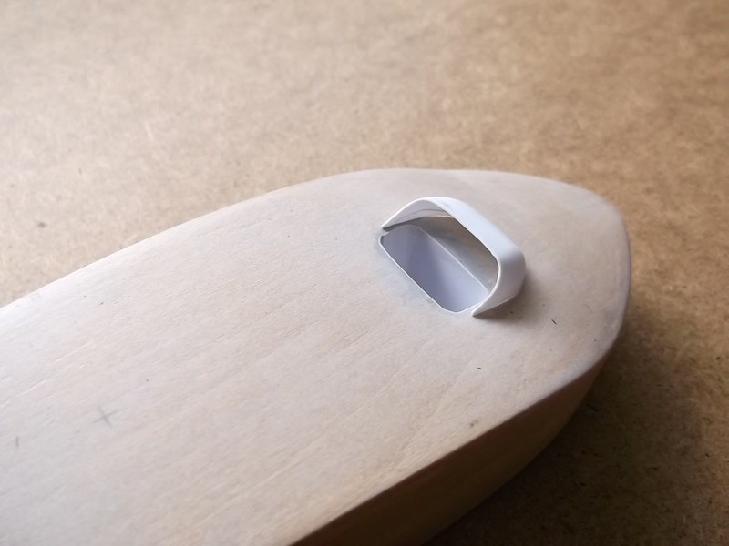
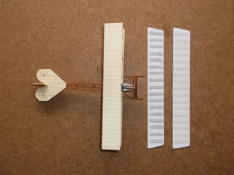
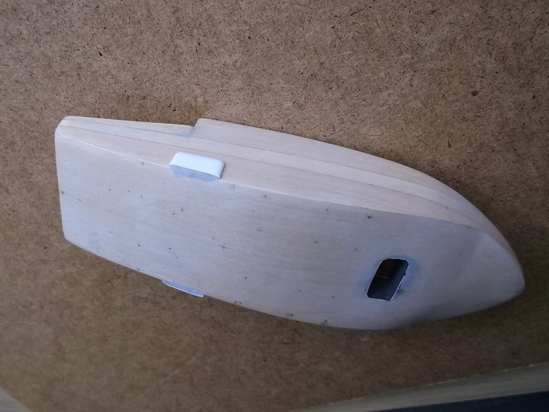
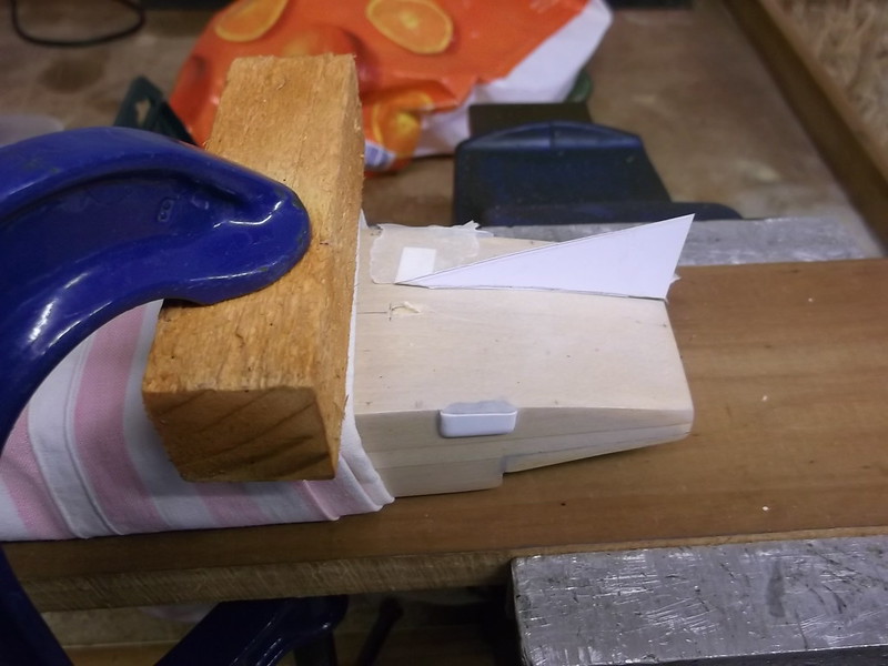
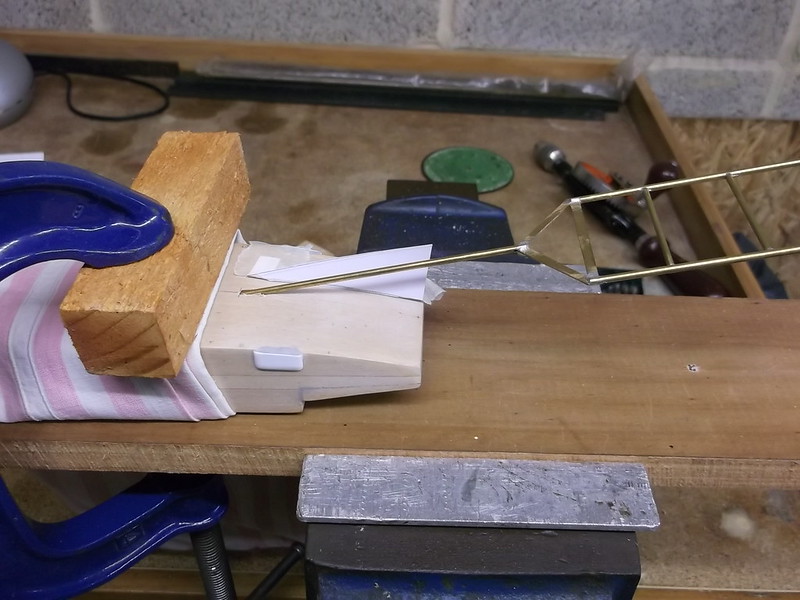
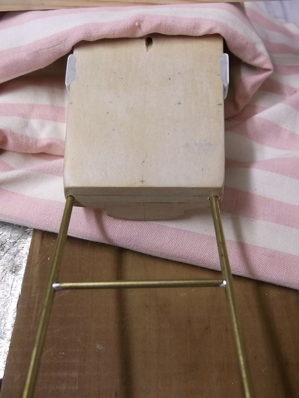
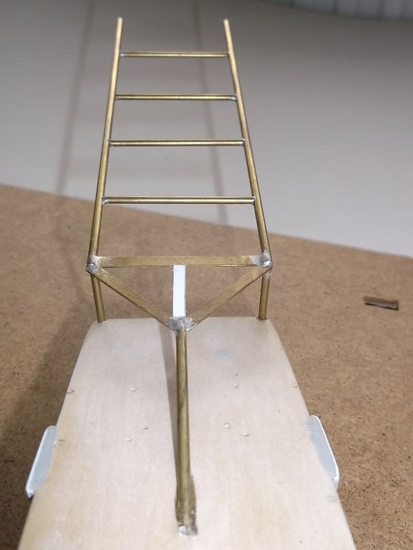
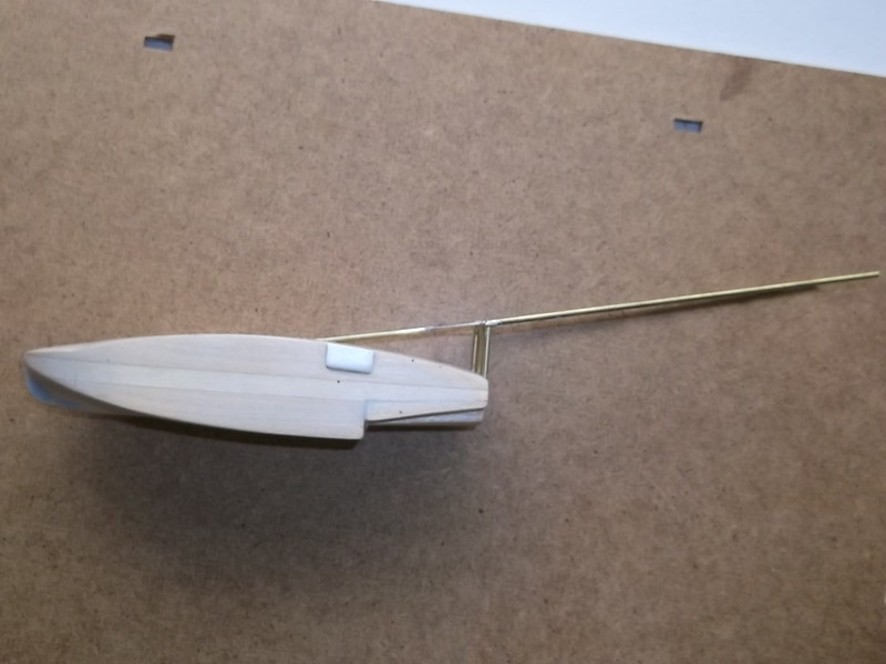
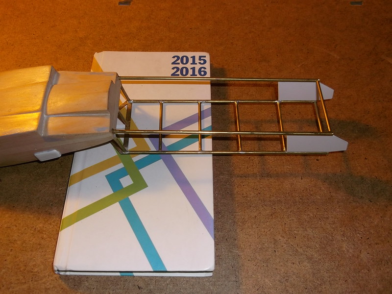
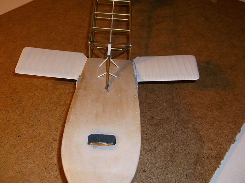
I have attached the booms and the stub wings to the hull so at last this is beginning to look like an aeroplane and not a lump of carved wood and pieces of plastic of assorted shapes and sizes. The first step was to attach the top boom arms to the hull. I laid the boom on to a set of plans and cut off the excess rod at both ends, leaving enough at the front end to be pushed about 2.5 cm into the hull. This will ensure that it does not move or fall out later.. The boom was supported by three upright posts at the very rear of the hull - these were made from brass rod and expoxied into holes drilled into the hull. These holes were drilled at the same time as others which will be used later for among other things, engine support struts, stub wings, and cabane struts. In all 41 holes of different sizes, and all had to be in the correct places - not 3mm or 5mm too much to one side or the other. I too can get cross-eyed when measuring so I made a tracing from the plans to show where all the holes on the top of the hull needed to go and transferred this to the model. I could then check each location and correct if necessary without finding later that I had mis-drilled one or two! The holes in the sides of the hull for the stub wings were easier as I will explain later.
Back to the boom: with the vertical posts in place I epoxied the front post and pushed this into the hole in the centre of the hull until the triangular section at the front of the boom sat directly over the posts. A quick dab of CA on the tops of the posts and put the boom on to the posts: the CA made sure that the boom did not move while the epoxy cured overnight. In the morning I added the centre strip in the triangle at the front end of the boom - this was from 15 tou plastic card held also held in place with CA.
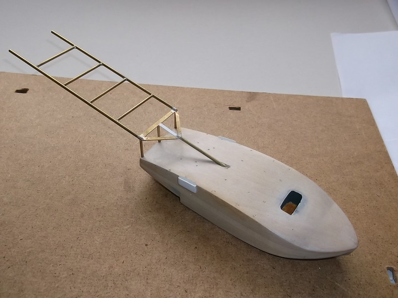
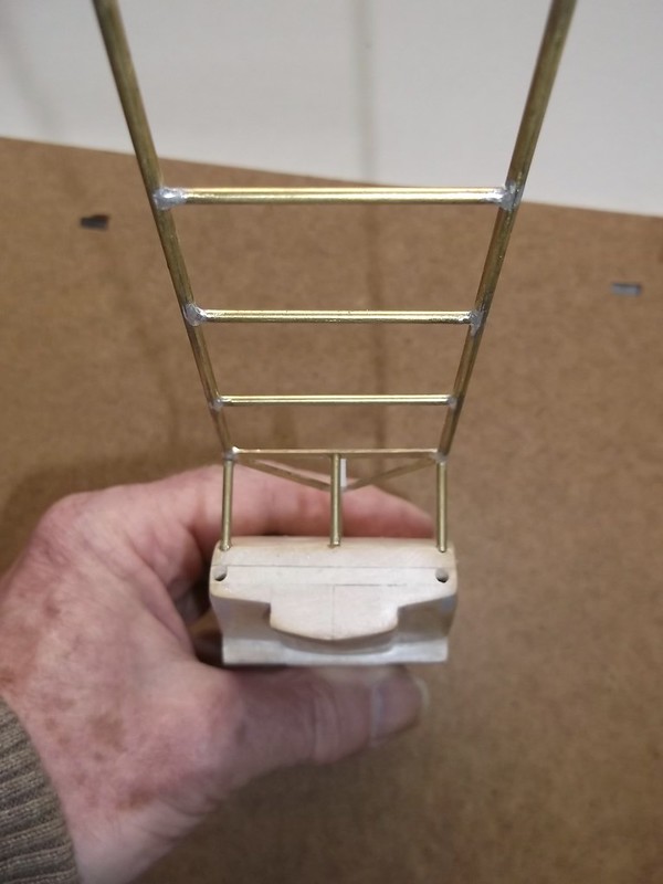
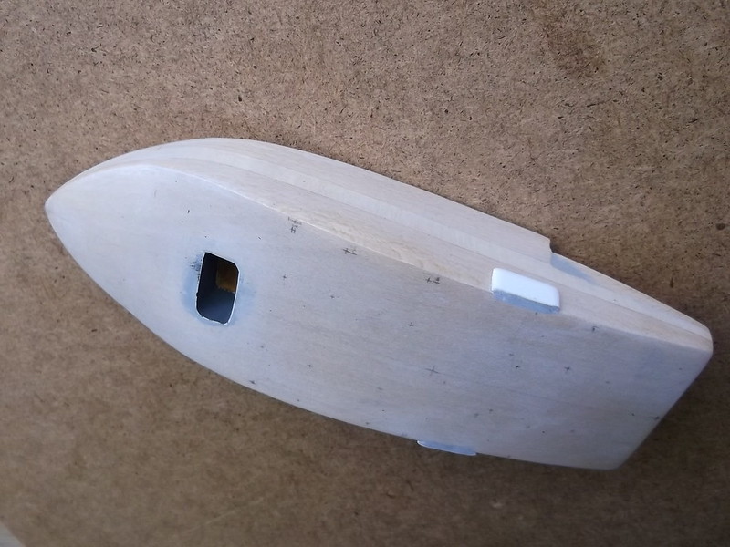
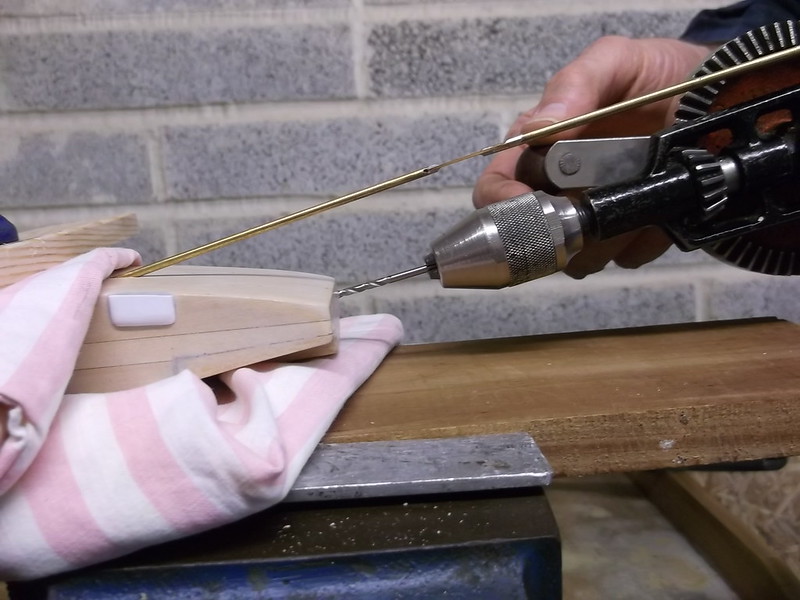
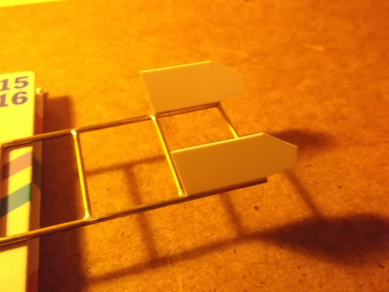
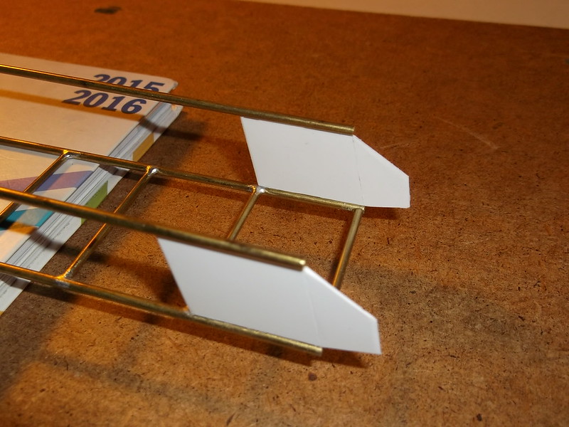
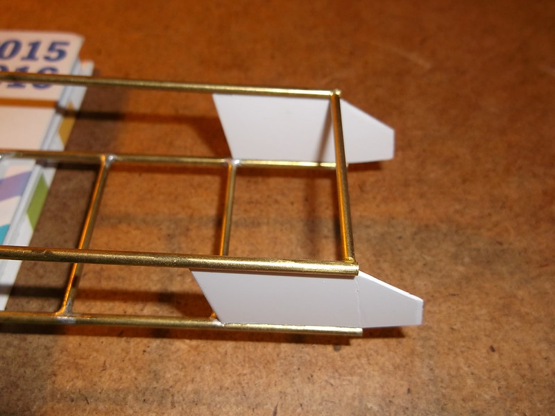
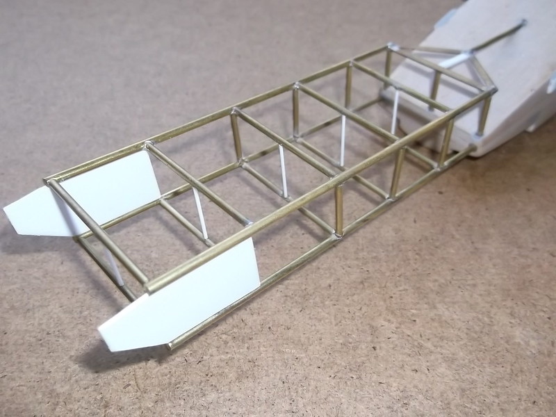
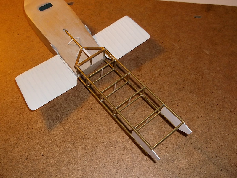
The last photo shows the holes where the lower boom arms will be inserted into the hull However before that stage I cut the fins from 30 thou card and rouned the leading and trailing edges: these were fabric wrapped around the boom struts so did not need to be either aerofiol section of very thin. These two pieces of card were CA'd to the underside of the upper boom arms:
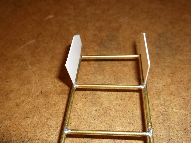
Now the lower boom arms could be epoxied into the rear of the hull and CA'd to the card fins. This method of using epoxy and CA means that the arms are securely fixed to the wood and plastic: I have some wriggle time to get the boom in the correct place with the epoxy, and when it is where I want it the CA holds it in place while the epoxy cures.
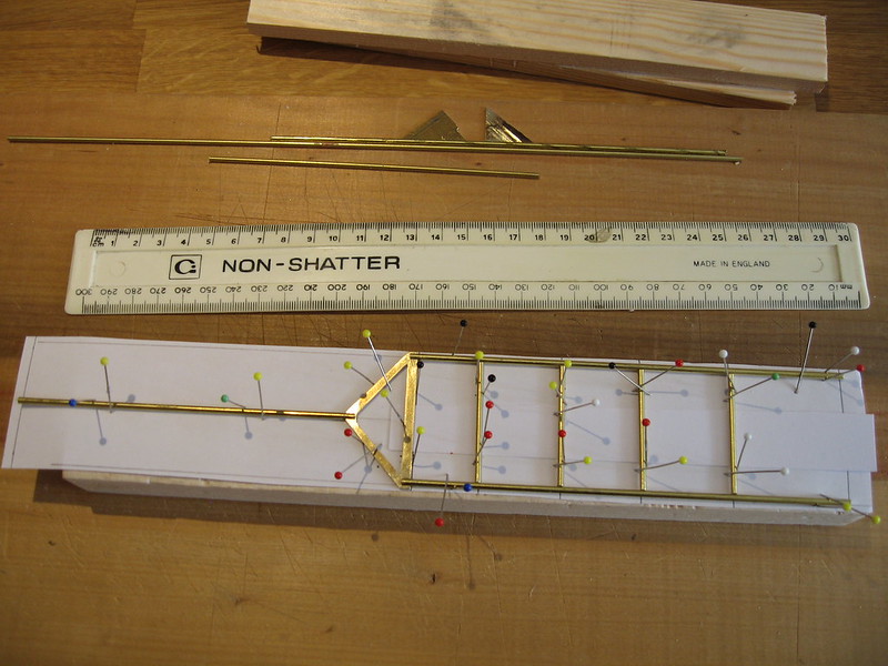
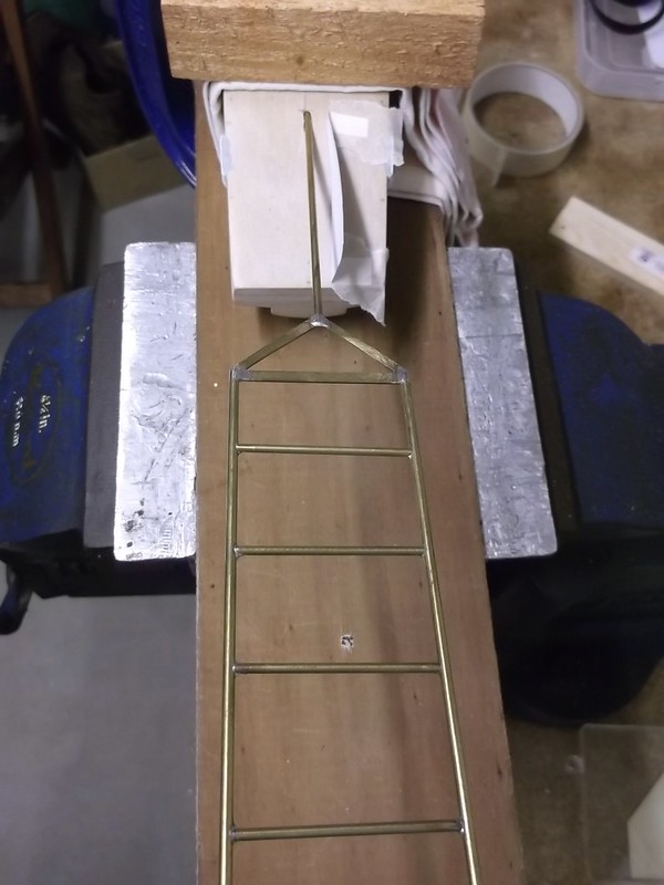
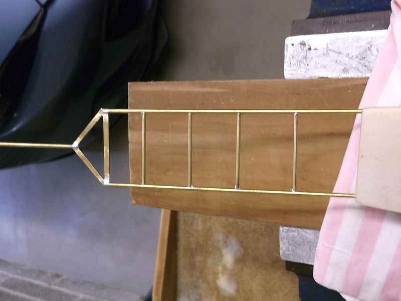
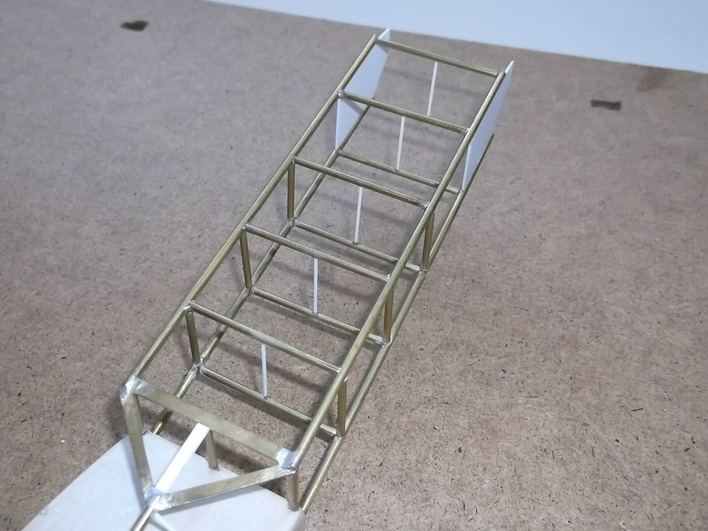
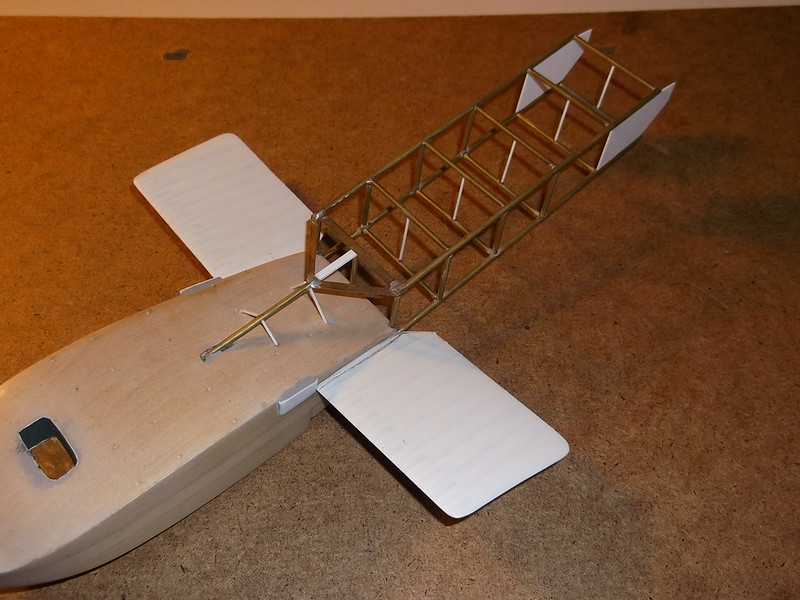
When the above was set and rigid I could add the remainder of the boom struts - vertical and horizontal. I started with the horizontal strut at the rear: I measured the gap with a pair of dividers, cut the rod and filed the ends with a round file to fit into the circular boom arm and CA'd it into place:
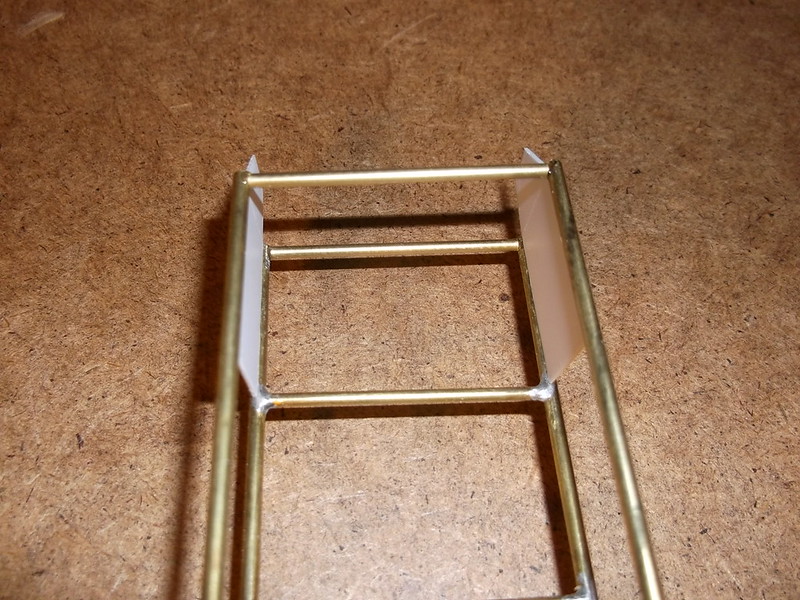
Having checked that all was square and true I was able to cut the remaining pieces of brass rod as per the above and glue into place. I finished by cutting the vertical centre posts from 20 thou plastic rod and CA'd them into place too:

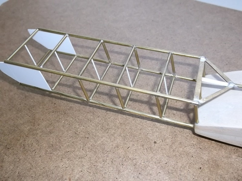
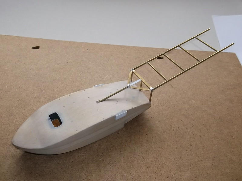
At last I have a structure which is beginning to look like a flying boat! There are alternative ways to do this but experience has taught me that making the parts as I go along is better in the end because I can measure everything to fit together exactly rather than finding that something is not quite square, the wrong length, too short, etc when the completed sub-assembly is tested against the other part of the model. I also used CA for the brass attachments because it was easier and safer than solder and a hot iron: imagine trying to hold the rod with one hand and solder and iron in another......and then get it all square and true!!!
The front arm of the boom was braced on each side by small struts which I represented with 15 thou rod. Of course holes had been drilled in the top of the hull to receive these.... Finally I added the stub wings at the rear of the hull. I had drilled two holes in the edges of each wing and inserted a piece of stiff wire which was held in place with CA. The wire ends were held against the hull to mark where the holes should be drilled. (This was actually done before I fixed the boom into place - I am describing it here to make it easier to follow). Add a drop of CA to the ends of the wires and insert into the holes in the hull. A little filler as necessary was run along the joint and the whole rubbed down and primed.
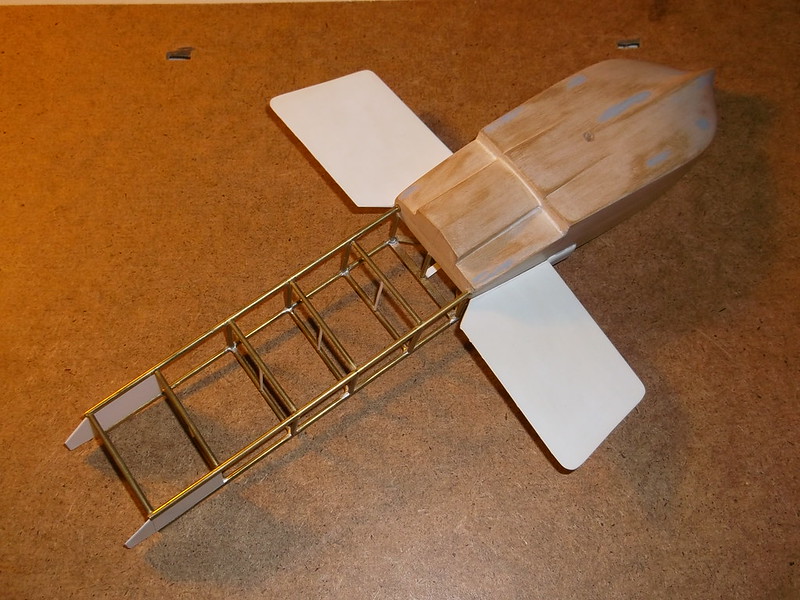
Thanks for looking. I am hoping that this next post will allow the reader to begin to see the shape of an aeroplane beginning to appear, but it wiil be a long time before the wing is put into place because of the structure of this particular machine - the wing was a parasol on cabane and large V struts mounted on the hull sides.
Thanks for looking.