Page 8 of 98
Re: Lone Modeller's Tray
Posted: December 22nd, 2017, 2:06 am
by skypirate
Yikes! Still gobsmacked by the superlative work going on here.
Cheers,
David
Re: Lone Modeller's Tray
Posted: December 22nd, 2017, 6:02 am
by Clashcityrocker
skypirate wrote:Yikes! Still gobsmacked by the superlative work going on here.
Cheers,
David
Same

Nigel
Re: Lone Modeller's Tray
Posted: December 22nd, 2017, 11:53 am
by JamesPerrin
Having read through this thread it's clear you are just making this aircraft up as you go along, using whatever comes to hand

Now that I can see what it looks like my brain is trying to reject it, what a bizarre looking machine!
Honestly, despite all the reworking of the struts, your work looks incredibly neat and tidy. Really looking forward to the completed model.
Re: Lone Modeller's Tray
Posted: December 22nd, 2017, 5:37 pm
by ShaunW
This is beyond good, LM and a great narrative too - seeing how you have approached fitting the wing with its attendant struts is an education in itself!
Re: Lone Modeller's Tray
Posted: December 27th, 2017, 9:40 pm
by Lone Modeller
Evening All,
Time has been pressing because while there are about 10 days to go until the end of the GB of which this is part, I do not have 10 days at home between now and January 7th so I have been spending as much time as possible trying to get this one done.....and I have succeeded as the following will I hope show.
First I completed the large under wing struts and bracing on the port (left) side, having made a new pair of longer struts for the purpose.
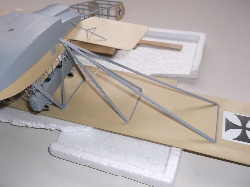
This meant that I could now rig both sides and I decided that this would be a good time to finish rigging the boom too.
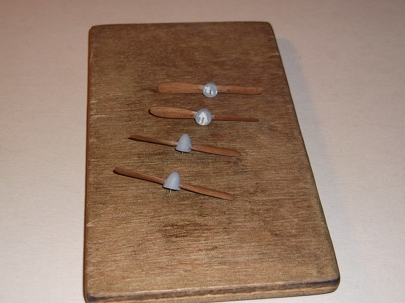
I have been making the propellors on and off during the build, and I had made the spinners at the same time as the cockpit screen, so it was time to put these together:
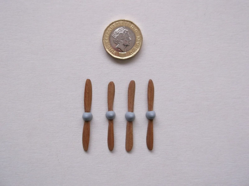
I realised that the propellors needed backing discs - easily sorted by marking out circles of the correct diameter with a pair of dividers on a sheet of 30 thou card and then cutting the circles out and finishing them with a file. These were glued to the backs of the spinners and any small gaps filled and the result painted again:
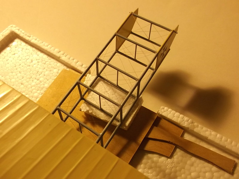
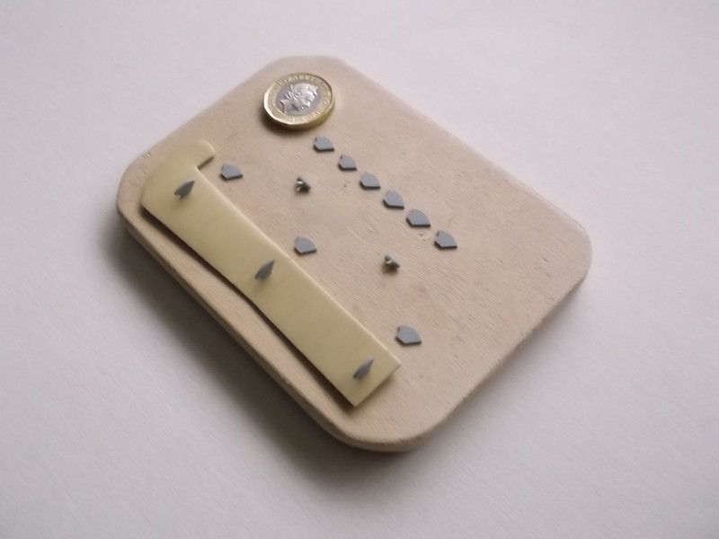
These were not fitted until the rest of the model was nearly finished. Next up were the small generators on the V struts: small pieces of 60 thou rod were shaped and propellors made from 10 thou card. Two small legs from 20 thou rod were added so that they could be secured to the struts. The aileron horns were cut from 20 thou card and shaped with round and flat files and glasspaper, and then painted. I have started to add them to the port (left) aileron in this image. The small pieces in the middle are the generators:

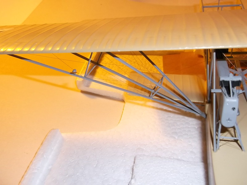
With the ailerons ready I inserted three small pieces of wire in holes which I had drilled into the leading edges of each aileron: the wires were held with CA. The other ends of the wires could then be inserted into holes in the trailing edges of the wing and also held with CA, and the control wires added to the horns. With the rigging finished it was time to go for the finish.... the propellors were added one at a time, again using wire to hold them in place in the nacelles. Two clear windscreens were shaped from some acatate sheet which was part of an old bubble pack from an Airfix kit from years ago - also CA'd into place. Last but not least I had to cut lengths of 30 thou plastic rod to add to the elevator sub-assembly so that this could be attached to the rear ends of the tail boom and the model is finished.
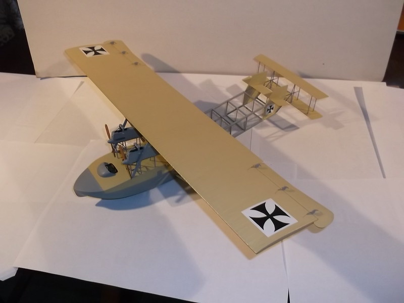
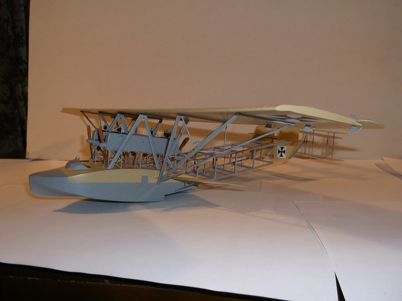
I am sorry about the quality of the photos but the light leaves a great deal to be desired at the moment and the weather is not suitable for taking this rather delicate model outside! I will post more photos in the aircraft section soon.
Re: Lone Modeller's Tray
Posted: December 27th, 2017, 9:59 pm
by iggie
Utterly amazing work throughout! It has been a pleasure and an education to watch this progress. Fantastic!
Re: Lone Modeller's Tray
Posted: December 29th, 2017, 11:58 pm
by skypirate
Run out of words of appreciation!
Bloody marvelous effort and result!
Cheers,
David
Re: Lone Modeller's Tray
Posted: December 30th, 2017, 5:42 pm
by Softscience
WOW!
I go away for a week and a whole boat materializes!
What do you rig with, and when rigging the bracing wires in the fuselage struts, do you drill holes in the strut junctions or do you just glue directly into the corner or other?
Re: Lone Modeller's Tray
Posted: January 4th, 2018, 7:55 pm
by Lone Modeller
Sorry for not answering sooner but I have been away for the New Year break visiting family.
Thank you all for the very kind comments - I am pleased that you have enjoyed following this build.
SS: I use 40 SWG rolled copper wire for rigging. I measure the length required from the model using a pair of dividers and cut off a piece which is slightly too long. I then roll it on a piece of wood using a length of brass strip: this makes the wire straight. I hold the wire to the model and eyeball estimate the length and cut it - sometime I need to trim twice, occasionally I need to cut a new piece! I use CA and I attach the wires directly to the location points: I do not drill holes because it would take too long and by using wire I do not need to make holes. Those fuselage wires were difficult to get into place on this model, but I can think of other models which I have made which had even more difficult wires to add. Sometimes (as in this case) I rig as I build because access may be very restricted or even impossible when the model is complete.
Re: Lone Modeller's Tray
Posted: January 4th, 2018, 8:40 pm
by PTB11
This is a lesson in model making!. Makes me think I should put my stash on eBay...

Fantastic work LM.
Re: Lone Modeller's Tray
Posted: January 4th, 2018, 8:55 pm
by Lone Modeller
PTB11 wrote:This is a lesson in model making!. Makes me think I should put my stash on eBay...
Fantastic work LM.
Thanks for the very kind remark PTB11.
(Don't tell anyone, but my stash went that way two years ago.......)
Re: Lone Modeller's Tray
Posted: January 4th, 2018, 9:52 pm
by TobyC
Blimey. I’m impressed to say the least.
Re: Lone Modeller's Tray
Posted: January 5th, 2018, 12:31 am
by Stuart
Wow! An outstandingly good bit of work!
Re: Lone Modeller's Tray
Posted: January 5th, 2018, 10:49 am
by ShaunW
This has been masterful and a great lesson in how to build a model but this type of work is probably beyond my modelling ability and is certainly beyond my patience threshold

It's a pleasure to watch someone who
can do it though, LM.
Re: Lone Modeller's Tray
Posted: January 8th, 2018, 11:04 pm
by Lone Modeller
Evening All,
Thank you Toby, Stuart and Shaun for the very kind remarks. I must write that I did enjoy building the Dornier, but now I have to do something something very different for me: I have got to make a base for the model. I do not wish to keep it in a large box in the roof, (why all the effort to scratch build the model if I do that?) and as the aircraft was launched and retrieved from Lake Constance on a trolley on rails, the trolly is an obvious feature to mount the model on. The model size is important - it has a span of approximately 17 inches (42cm), and a length of 14 inches (35cm), which means that it will not fit into the display cabinets in which I usually keep my models. Consequently I have bought a perspex covered base and I want to put a small display in it. The aircraft model will sit on a trolley on a turntable which was built outside the front of the hangar/workshop at Seemoos on Lake Constance which was an old Zeppelin shed in which Claudius Dornier's early flying boats were built when he was working for Graff Zeppelin. I will include a short section of the ramp along which the flying boats were taken to the lake for launching and retrieval, and part of the hangar floor. The display will be based on photographs taken between mid 1915 and late 1918 and published in Windsock DataFile no 136: Dornier Flying Boats. One set of photographs in particular, taken in May 1917, will be used for some specific details as it is clear that there were changes made between 1915 when the turntable and ramp was built and 1918 when the last of the photographs was taken. I am not trying to make a 100% accurate replica: rather this is simply to set off the model aeroplane in a realistic context. This is the first time that I have attempted anything scenic so it will be a steep learning curve for me and I do not doubt that I will be making mistakes along the way, but as the person who never made a mistake never made anything, here goes.
First here is the base which I bought from Just Bases (I have not included the perspex top):

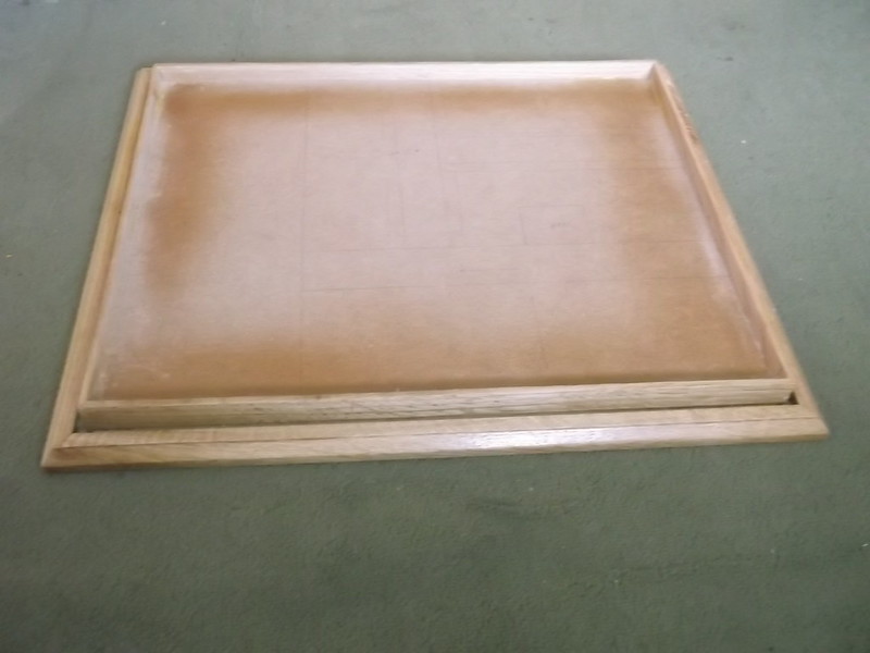
The dimensions of the display area of the base are 21 inches (53cm) x 13 1/2 inches (33cm) which will be large enough for the model aeroplane to sit in it and leave space to put the perspex cover over without hitting it.
When I told to my brother and a member of my modelling club of my intention to mount the aircraft on the turntable, they both asked would the latter be motorised! I have to admit that this was not my original intention, but it happens that the turntable was built on the top of a steep bank, so I investigated the possibility of putting a motor under the scenic base. Careful measurement showed that it would be possible:
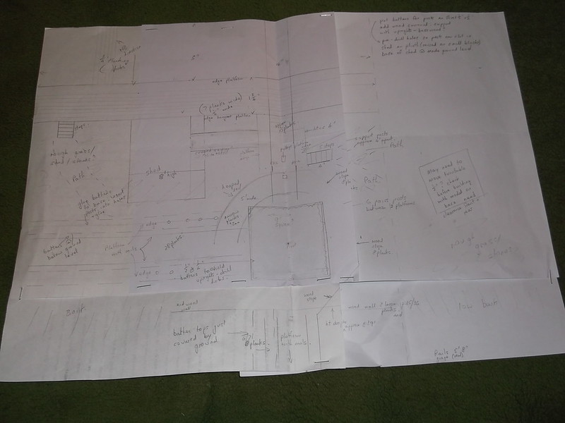
This is my working plan for this display: it is 1:1. The square is where the motor will be ie under the turntable. The two arcs on the top left are part of the platform that surrounded the turntable ,and the other lines represent platforms and a shed, steps, hangar workshop floor, etc, all of which have been drawn to scale based on the photographs mentioned. The right side of the display area will be left clear so that I can put some explanatory notes about the aeroplane and setting for viewers. The various notes on the plan are for ideas that I have concerning how I might make this - I may of course change some things as I go along. Having a turntable motor would have an advantage that I had not forseen. The aircraft model is quite heavy as it has a wood hull, brass boom at the rear and a large wing made of laminated 60thou plastic card sheet. If this was to be mounted on a railway trolley it would need something fairly strong to hold it in place. By drilling a hole in the bottom of the hull and inserting the turntable shaft, I would have a hidden strong and stable support while the trolley would be what the viewer would see. I drilled the necessary hole in the underside of the hull when I was making the model, after one model railway turntable kit had been purchased:

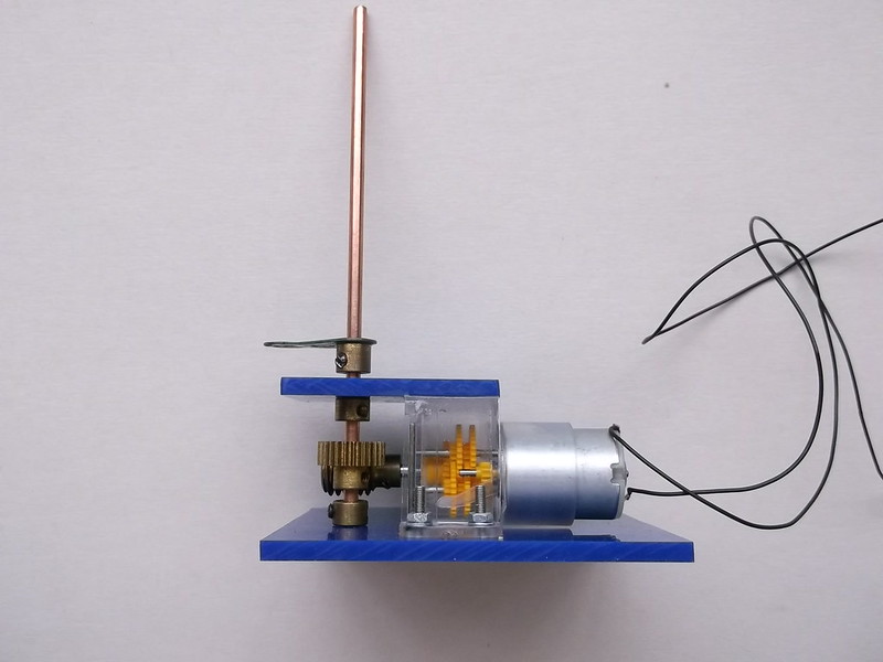
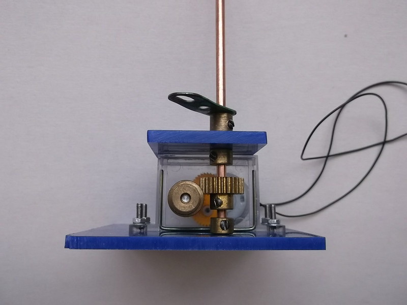
Testing of the gear assembly for this kit showed that the gear drive to the vertical shaft, which is plastic, would be too weak and would quickly wear. Given that this motor is not going to be accessible when the base is finished I decided that the gears would be better if they were replaced with something more durable: some of my brother's old Meccano gears were therefore pressed into service. (Well he suggested motorising in the first place so he could help find a solution to a problem that motorisation raised). Here is the unit, showing the gears on the vertical drive shaft and original plastic gears inside the clear perspex box of the motor. You can also see that my brother and I have built a stronger and more stable perspex surround (blue) so that this unit can be screwed to the display base:

Now I have to fix the motor to the base and some wood strips which will have holes drilled into them to hold the ends of dowels which will represent the posts which supported the various platforms.
Thanks for looking.