IPMS Austria 1/33 TSR.2
-
SJPONeill

- Modelling Gent and Scholar
- Posts: 3525
- Joined: May 1st, 2011, 12:01 am
- Location: Near the Spiral, NZ.
- Contact:
IPMS Austria 1/33 TSR.2
Just setting up a continuation thread for this build from last month's TSR.2 GB... http://uamf.org.uk/viewtopic.php?f=273&t=9363
Please critique my posts honestly i.e. say what you think so I can learn and improve...
The World According To Me
The World According To Me
-
SJPONeill
- Modelling Gent and Scholar
- Posts: 3525
- Joined: May 1st, 2011, 12:01 am
- Location: Near the Spiral, NZ.
- Contact:
Re: IPMS Austria 1/33 TSR.2


At the end of the last episode our hero had finished (for now) with the tail section and was focusing his efforts on the mid-fuselage around the intakes...the intakes themselves had been folded and fitted into shape and test-fitted with the turbine fan pieces in position...
Our story continues...
I too am impressed with just how effective the 2D printed turbine fan parts are - they look pretty good at the end of the intakes where you can only view them from one perspective...This is an approach that I think would also work well for detailing other areas that an observer can not easily see into, undercarriage bays for example...

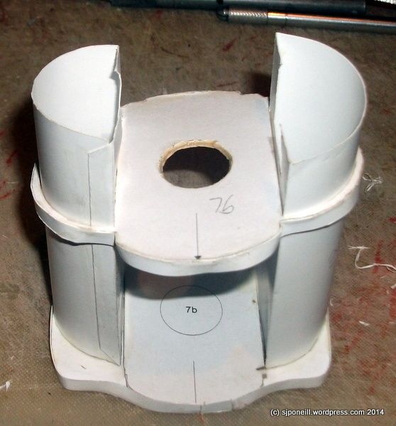
By squinting my eyes and twisting my head while looking at the instructions, and by comparing the length of the intakes against the length of the adjacent fuselage skin, I have worked out that the intakes penetrate the former 7b and protrude by a couple of centimeters...

Unfortunately the intakes seem slightly too large for the holes cut for them in the fuselage former part 7b. Because the turbine fans also appear slightly under-size I am hypothesising that some how both intakes have been assembled with some error that makes then just a smidgen too large. If I can not see where the error is I may reprint the parts and try them again to see if I can prove the problem to either design or builder...
As a Plan B, I have also soaked the inner edges of the intake cut-outs in part 7b with the PVA woodworking glue so that I can, if necessary, sand the edges back to make the hole slightly larger to accept the intakes as they are currently sized...
Please critique my posts honestly i.e. say what you think so I can learn and improve...
The World According To Me
The World According To Me
-
splash

- Senior Service Rotorhead
- Posts: 13828
- Joined: May 1st, 2011, 11:02 am
- Location: Somerset England
Re: IPMS Austria 1/33 TSR.2
Those intakes are impressive as you say the 2d printing works really well
Regards Splash
Regards Splash
My work bench is starting to look like Portsmouth Naval Dockyard.
-
SJPONeill
- Modelling Gent and Scholar
- Posts: 3525
- Joined: May 1st, 2011, 12:01 am
- Location: Near the Spiral, NZ.
- Contact:
Re: IPMS Austria 1/33 TSR.2

It took me a good couple of hours of carefully fettling the intakes into place. I could not seem any glaringly obvious flaw or fauz pas that has lead to their slight oversizeness but next time I will shave about 1mm off the width and the same off the curved face...They are a pretty tight fit and I was careful to do as little damage as possible to the forward face of the intake as I endlessly (or so it seemed) presented the intake to the space it has to fit into and 'encouraged' it too fit...Looking back I guess that I could have used the rearmost face to fit as I think that the surfaces are all parallel.
I mounted the turbine fans on some scrap card and fitted some temporary handles to enable me to place and hold them in the right position until the glue dried. The intakes are also too big for the fans to be a close fit which is why I am leaning towards their oversizedness being something in their design or construction.

In the Mr Men series, I am Mr Blurry...The intakes are still just sitting in place until I am sure that I have calculated their correct position and I will know that when I start to attach the skin for this section...
Please critique my posts honestly i.e. say what you think so I can learn and improve...
The World According To Me
The World According To Me
-
SJPONeill
- Modelling Gent and Scholar
- Posts: 3525
- Joined: May 1st, 2011, 12:01 am
- Location: Near the Spiral, NZ.
- Contact:
Re: IPMS Austria 1/33 TSR.2
http://www.ecardmodels.com/index.php/1- ... model.html
If anyone wanted to tried a more challenging approach to a jet engine this may be of interest...up to you if you want to then build an aircraft around it...
If anyone wanted to tried a more challenging approach to a jet engine this may be of interest...up to you if you want to then build an aircraft around it...
Please critique my posts honestly i.e. say what you think so I can learn and improve...
The World According To Me
The World According To Me
-
SJPONeill
- Modelling Gent and Scholar
- Posts: 3525
- Joined: May 1st, 2011, 12:01 am
- Location: Near the Spiral, NZ.
- Contact:
Re: IPMS Austria 1/33 TSR.2

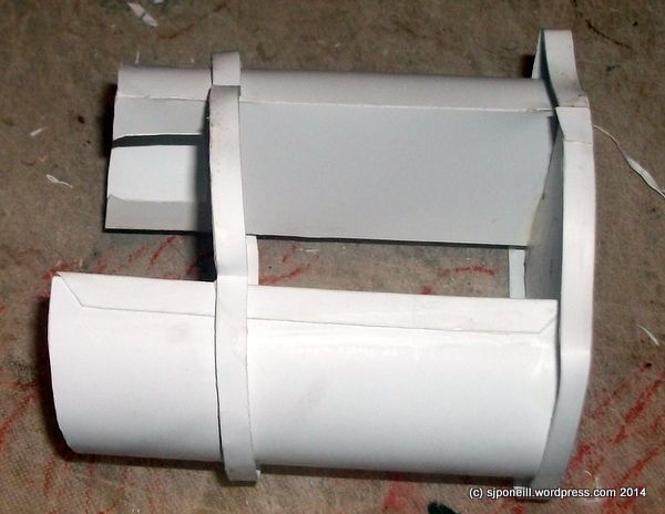
Last night I added an additional former to the rearmost former that the intakes will butt up against to ensure that they remain parallel; and added the joining strips around the next two formers to be skinned (tonight's mission)...
Please critique my posts honestly i.e. say what you think so I can learn and improve...
The World According To Me
The World According To Me
-
SJPONeill
- Modelling Gent and Scholar
- Posts: 3525
- Joined: May 1st, 2011, 12:01 am
- Location: Near the Spiral, NZ.
- Contact:
Re: IPMS Austria 1/33 TSR.2
Didn't make any progress on Tuesday night...had a late dinner, watched NCIS and then got roped into The Hunger Games...caught up last night...
Attached the intakes to the rear former and the extra space that I added...but...
...somehow...the intakes have come out with one side having the long edge on the bottom and the other having it on the top like they were not 'handed'...how I managed this has me absolutely confounded - and, of course, I only notice AFTER they were firmly fixed in place. The forward former in this pics is just sitting in place so it is not that...I can slice off and replace the offending sections but it just ANNOYS me so much that I seem to have made some form of uber-elementary mistake...(and while watching 'Elementary' too!!)
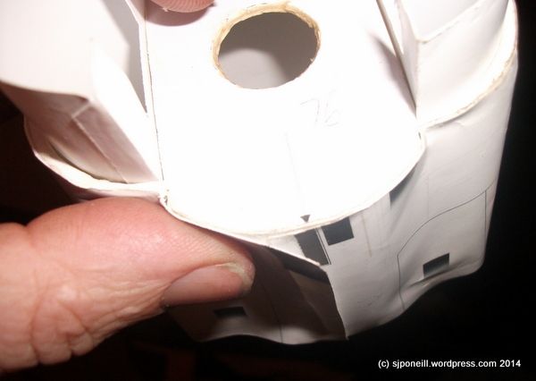
I used the next skin section to determine the correct spacing between the intake formers and worked my way around both formers, glueing the skin down. When I got to the end of the skin on the forward former, I had an overlap of about quarter an inch... forgot to add the joining strip to the former: this shows the impact that even leaving off one thin layer of paper can have on the design as the extra width NOT provided in this case by the joining strip to the former, translates directly to the overlap error...!!!
Whereas, the rear former with the joining strip has almost no overlap...attention to detail and accuracy in cutting rule in paper modelling!!!
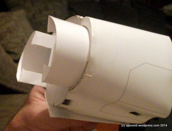
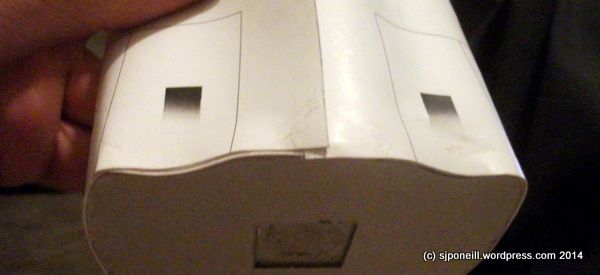
This shows off the intake error in all its brutal glory...amazingly, even though I forgot to precurve the skin, it went on fairly painlessly...
Here I making a couple of additional formers for the fuselage section that will link this...
...with...
...this, the nose gear section...
Tune in tonight for the next stage in this 'comedy' of errors...

Attached the intakes to the rear former and the extra space that I added...but...

...somehow...the intakes have come out with one side having the long edge on the bottom and the other having it on the top like they were not 'handed'...how I managed this has me absolutely confounded - and, of course, I only notice AFTER they were firmly fixed in place. The forward former in this pics is just sitting in place so it is not that...I can slice off and replace the offending sections but it just ANNOYS me so much that I seem to have made some form of uber-elementary mistake...(and while watching 'Elementary' too!!)

I used the next skin section to determine the correct spacing between the intake formers and worked my way around both formers, glueing the skin down. When I got to the end of the skin on the forward former, I had an overlap of about quarter an inch...

Whereas, the rear former with the joining strip has almost no overlap...attention to detail and accuracy in cutting rule in paper modelling!!!

This shows off the intake error in all its brutal glory...amazingly, even though I forgot to precurve the skin, it went on fairly painlessly...

Here I making a couple of additional formers for the fuselage section that will link this...

...with...

...this, the nose gear section...
Tune in tonight for the next stage in this 'comedy' of errors...
Please critique my posts honestly i.e. say what you think so I can learn and improve...
The World According To Me
The World According To Me
-
skypirate

- Modelling Gent and Scholar
- Posts: 7300
- Joined: May 1st, 2011, 6:13 am
- Location: Port Macquarie, Australia
Re: IPMS Austria 1/33 TSR.2
Good grief!
This is a job and a half!
David
This is a job and a half!
David
-
SJPONeill
- Modelling Gent and Scholar
- Posts: 3525
- Joined: May 1st, 2011, 12:01 am
- Location: Near the Spiral, NZ.
- Contact:
Re: IPMS Austria 1/33 TSR.2
That's what the angle grinder said before it ran off and hid...
I've reprinted the parts sheet with the intakes on it: it has a lot of the fiddly bits from the undercarriage on it so I figure I'll need at least one additional copy of it. On examining the parts unfolded, I think that I have folded one of them inside which has created the gross error on the starboard intake...I'm not sure if I'll get to it tonight as I am playing with the cockpit at the moment, but hope to have the intakes ticketybooed by Monday...
I've reprinted the parts sheet with the intakes on it: it has a lot of the fiddly bits from the undercarriage on it so I figure I'll need at least one additional copy of it. On examining the parts unfolded, I think that I have folded one of them inside which has created the gross error on the starboard intake...I'm not sure if I'll get to it tonight as I am playing with the cockpit at the moment, but hope to have the intakes ticketybooed by Monday...
Please critique my posts honestly i.e. say what you think so I can learn and improve...
The World According To Me
The World According To Me
-
SJPONeill
- Modelling Gent and Scholar
- Posts: 3525
- Joined: May 1st, 2011, 12:01 am
- Location: Near the Spiral, NZ.
- Contact:
Re: IPMS Austria 1/33 TSR.2

The intake parts in their natural environment...the more I look at these, the surer I am that my error was as simple as folding one the wrong way...

Last night, I concentrated on deciphering the instructions for the ejection seats. Each comprises a number of parts but the relationship between them isn't that clear...
As a general rule, I am not a big fan of seat belts molded or printed directly on the the seat itself and I think that the designers would be doing us a favour by defaulting to either no belts or separate belts. When I do this kit again, I will plan on upsizing something like the Eduard 1/48 TSR.2 belts to 1/33 to get a better 3D effect although it is not like you can see much in the cockpit especially the rear one...
Please critique my posts honestly i.e. say what you think so I can learn and improve...
The World According To Me
The World According To Me
-
SJPONeill
- Modelling Gent and Scholar
- Posts: 3525
- Joined: May 1st, 2011, 12:01 am
- Location: Near the Spiral, NZ.
- Contact:
Re: IPMS Austria 1/33 TSR.2

These are the instructions for the TSR.2's cockpit area...there is also a line of text on another sheet that pretty much only says "...assemble parts XX-YY...". As you can see there is not much guidance as to sequence or layers...

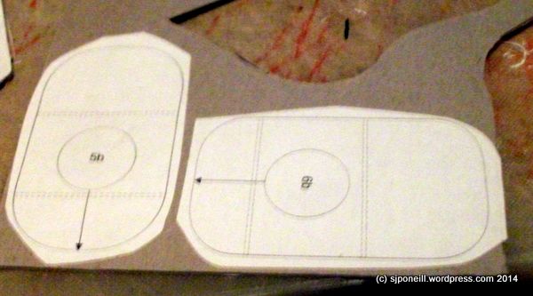
These are parts 69c...with the benefit of hindsight, I think that these are meant to wrap around the former parts for the seats: the white rectangular area is meant to be cut out around the detent at the front of the seat cushion where the ejection seat handle would go...I think...

Here, I have glued the 69c parts to the seat cushions that I had already started to assemble, having cut off the section that would, otherwise have covered up the lower seatbelts on the cushion. Apart from physically joining these two parts, I don't see what value part 69c actually adds...

The seats with the excess 69c sections removed...the little angle bits fit around the inside of the detent where the ejection seat handle would go...

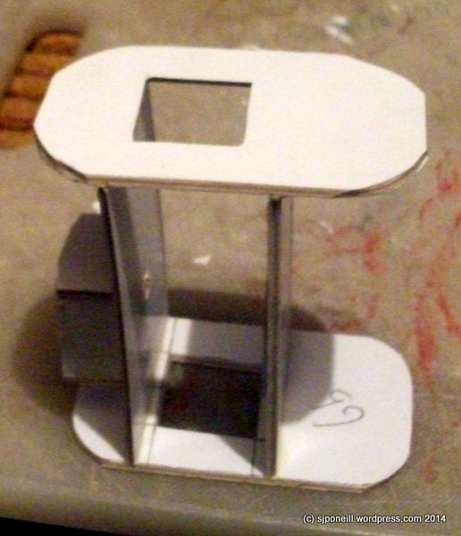
I kinda screwed up a little and attached the seat cushions to each other so that they were perpendicular to each other. The parts 69a that look like ice hockey clubs are the sides of the seats and given then the correct angle. Fortunately, I was still able to induce some bend into the join between the cushions to fit the parts 69a into position.

The pilot's seat squeezed into the forward cockpit where the adjusted angle of the seat back does confirm to the slope of the bulkhead at the rear of the cockpit. I suspect that there is a former that fits on the back of this bulkhead for strength...

The WSO's cockpit...I think that parts 4c and 54d fit on the backs of the instrument panel and the rear bulkhead respectively...the plans/instructions are not very help in this regard...If they do, then it would not be an unreasonable expectation for there to be a horizontal former that runs between them to support the cockpit floor and add further strength to the overall structure...
Even though not much can be seen through the teeny windows when the cockpit is complete, I am toying with printing another copy of the instrument panel, cutting out the instruments and adding them to the 2D one for a little implied 3D depth...(much) later on, I may look at upsizing some of the aftermarket for the Airfix TSR.2 to see if I can make a better representation of the actual cockpit than that supplied in the original model...
Please critique my posts honestly i.e. say what you think so I can learn and improve...
The World According To Me
The World According To Me
-
SJPONeill
- Modelling Gent and Scholar
- Posts: 3525
- Joined: May 1st, 2011, 12:01 am
- Location: Near the Spiral, NZ.
- Contact:
Re: IPMS Austria 1/33 TSR.2
PS I am also thinking that I should add the clear layer for the windows before curving and fixing the wrap-around cockpit roof in place...
Please critique my posts honestly i.e. say what you think so I can learn and improve...
The World According To Me
The World According To Me
-
SJPONeill
- Modelling Gent and Scholar
- Posts: 3525
- Joined: May 1st, 2011, 12:01 am
- Location: Near the Spiral, NZ.
- Contact:
Re: IPMS Austria 1/33 TSR.2

Last night I added reinforcing formers to the WSO's cockpit...quite recently, I sighted a piece of thin clear sheet plastic that would be just the thing for the cockpit glazings - I just have to remember where I put it for 'safe' keeping...

I added joining strips to the next lot of formers to be skinned to (hopefully) ensure the best skin fit around the formers...

...and prepared the next lot of skins. This will cover the area between the intakes to just aft of the cockpit...
Please critique my posts honestly i.e. say what you think so I can learn and improve...
The World According To Me
The World According To Me
-
SJPONeill
- Modelling Gent and Scholar
- Posts: 3525
- Joined: May 1st, 2011, 12:01 am
- Location: Near the Spiral, NZ.
- Contact:
Re: IPMS Austria 1/33 TSR.2

EDIT added the morning after
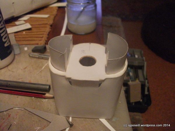
I left this pic off yesterday's update...showing the start oif the processing wrapping the skin around the nise gear section...

Tangible progress last night as I skinned the next two fuselage sections...no major dramas (for a change) and only some minor fit issues that were resolved through brute force. I think that one of my horizontal formers was a tad too long and this threw out the fit just a tad...

The other ends...although the kit provides full main gear bays, it only provides a little box with no detail liner for the nose gear bay...The section on the left has yet to be finished so the skin has yet to be attached to the sides of the former. I wasn't too sure whether this former needed a joining strip or not - the instructions don't show one -and after test fitting I decided to go without one. Looking back a joining strip probably would promote a tighter fit but I'd call it an option. I think that what appears to be excess circumference in the skin in this pick will be drawn in the the two small intake detents at the top of the former.

The black former on the left is a cut down version of the main intake former. I am going to add this to provide a firm mating surface with the main fuselage.

The main fuselage sections just sitting in sequence next to each other. Possibly it is starting to look like an aircraft...also starting to get a feel for the size of the completed model...
Please critique my posts honestly i.e. say what you think so I can learn and improve...
The World According To Me
The World According To Me
-
SJPONeill
- Modelling Gent and Scholar
- Posts: 3525
- Joined: May 1st, 2011, 12:01 am
- Location: Near the Spiral, NZ.
- Contact:
Re: IPMS Austria 1/33 TSR.2

A slower night last night...added the rearmost former to the fuselage section that sits between the intakes. This is a modification that I have made to provide a broader mating surface between this section and the one aft of it...

Now starting to think into the windows. I had a spare part of the wrap-round section for the WSO's cockpit and have used this as a template for a similar wrap-around clear sheet that will act as both the WSO's windows and also strengthen this section..I'll coat it in Future before laminating it to the actual part.

Also thinking into the pilot's glazings as well...
Please critique my posts honestly i.e. say what you think so I can learn and improve...
The World According To Me
The World According To Me