I do not normally take a lot of photos as I build, unless I am making a lot of changes to a kit and need to remember what I did to make another one! That was the certainly case with this kit! The Airfix Churchill is a kit that provides a lot of opportunity to do as much, or as little extra as you want to (or are compulsively driven to do in my case). Hopefully this will be of use to someone else...
I started with the excellent guidance provided by
Nikolas Lloyd
I also used:
“Churchill Crocodile Flamethrower” by David Fletcher and Peter Sarson from New Vanguard; Scale drawings by George Bradford from
“British Armored Fighting Vehicles” as well as numerous photos found on the internet.
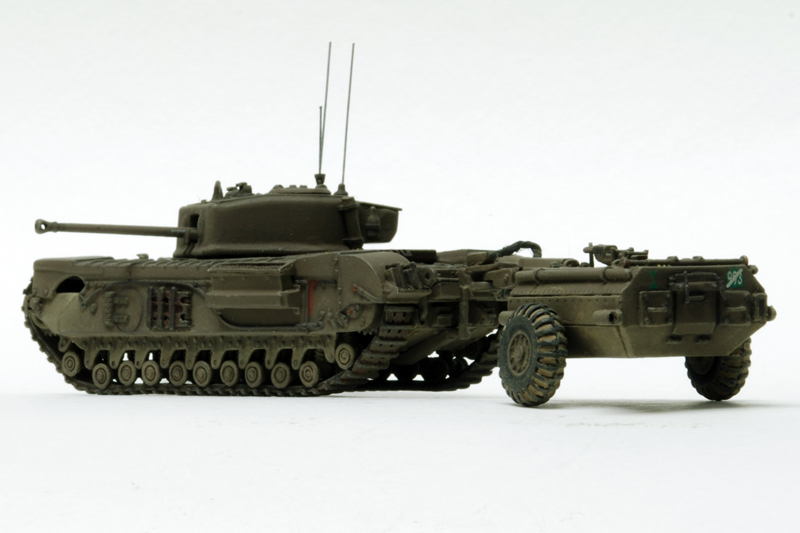
First, the Churchill Tank:
I completed the wheels as described in the entry above. The side pieces are slightly warped and do not fit well. I gently bent the left one to level the top mudguard section. I applied the base coat of paint and painted the tracks before I finally glued the sides on and used modeling putty to fill the gaps along the joins between the top edge of the main hull and the sides.

Following Lloyd’s instructions, I removed the two hull periscopes and the vestigial air vent and replaced them with three new periscopes made from Evergreen rod, two tall and one short. The new air vent was carved from Evergreen sheet.

The flame projector supplied with the kit is too big and the wrong shape compared to wartime photos. I cut it back and increased the front angle on top. This looks closer to the photos I have seen, but it is still bigger than George Bradford’s drawing. I also added the counter-balance plates on the top.

I carved the front towing eye to shape and bent brass wire into the u-shaped shackle. This probably should have been made from thicker wire, as it looks too small and thin.

After much procrastinating, I finally decided I would replace the headlights. They were carved from rod, but too late in the process to easily remove all the residue from the Airfix ones. Ah well, next time. The Headlights were mounted further forward on the protruding rib, matching a wartime photo.

Since I chose to remove the front mudguards, I needed to add four Idler adjustment assemblies. These were made from thin rod, filed flat after they were glued in place. The large center bolts were made from a bigger diameter rod and the hexagonal shape filed into them, also after attaching. Also shown here, I increased the lower front angle of the outer sides and removed the molded bolts below the debris hole. The Airfix kit in this area seems to match earlier Churchill versions, rather than all the Mk VII I have seen.

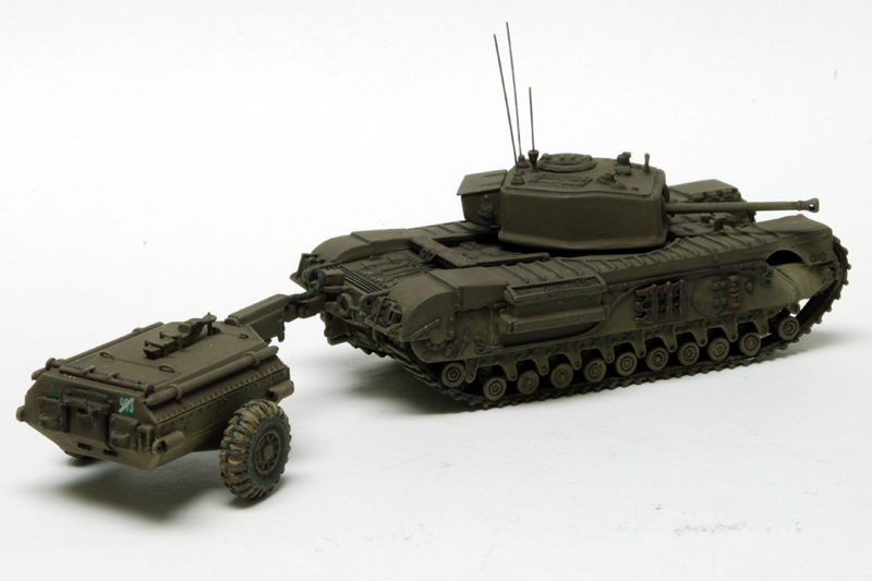
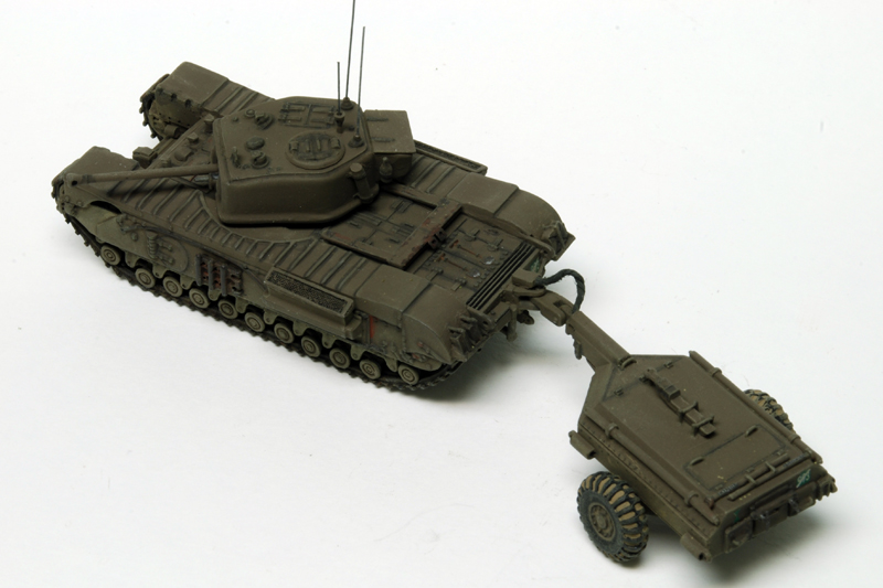
Moving to the rear, I again followed Lloyd’s instructions and added the ‘flimsy’ oil cans and shelf on the left mudguard and the water Jerry Can and shelf on the right mudguard. The cans were from Milicast. I made the telephone box to the left of the trailer hook, from thick sheet and scribed a line for the lid. The photo example I found did not show any hinges, but did have a small projection on the top where the wire emerged to go into the tank. The two smoke generators underneath were made from sheet and square section rod. I drilled holes in the sides for the towing shackles, again made from wire. I cut down the supplied flame tank towing hook width, but it is still too wide.

The normal towing pintle, visible below the Crocodile addition was carved from sheet. This view shows the added wire mesh on the air intakes and frame. Some photos I have seen seem to show mesh, while others show a series of slits parallel with the short sides. Again, I used very thin rod for the frame and filed it flat afterwards. I chose not to add rain covers over the air intakes, as they were not always fitted and I wanted to see the mesh, having added it. This view also shows the drilled holes in the exhaust outlets.

This addition I deliberately left until after finishing painting, decals and weathering. This was a hinged clamp for the Crocodile articulated tube/hitch (part of the trailer assembly in the kit) to hold it steady when the trailer was not attached.

For the turret, I followed Lloyd but deviated some too. The supplied main gun barrel is too short, too thin and out-of-round, so I replaced it with an excellent brass one from Milicast. The splash guard bulges on either side of the gun were made with modeling putty over small rectangles of sheet. In George Bradford’s drawings and the photos I have, these seem relatively small mounds, rather than a curve out to perpendicular flat faces alongside the gun opening, as shown in Lloyd’s pictures. I made the sighting vane from wire, after many attempts to carve one thin enough from sheet. Still too thick, but better!

The bottom turret ridge was added from sheet, with modeling putty to smooth the transition, sanded to a v-shape. The side joins of the turret front plate needed to be filled and sanded to blend properly with the turret sides to look like a homogeneous casting. Per Lloyd, I added the map case, two fire extinguishers and the golf-tee aerial mount, sized from George Bradford’s drawings. The three aerials will be added after painting.

I cut the flat in the front of the molded air vent and added tops to the periscopes, but probably should have replaced them. In fact, after taking this picture, I did replace the air vent. The additional bolts were added per Lloyd and located per George Bradford. I decided to keep the old style cupola, as some photos of Mk VII seem to show it, as did GB’s drawings. However, I believe most Mk VII got the new design cupola with all-round vision periscopes?
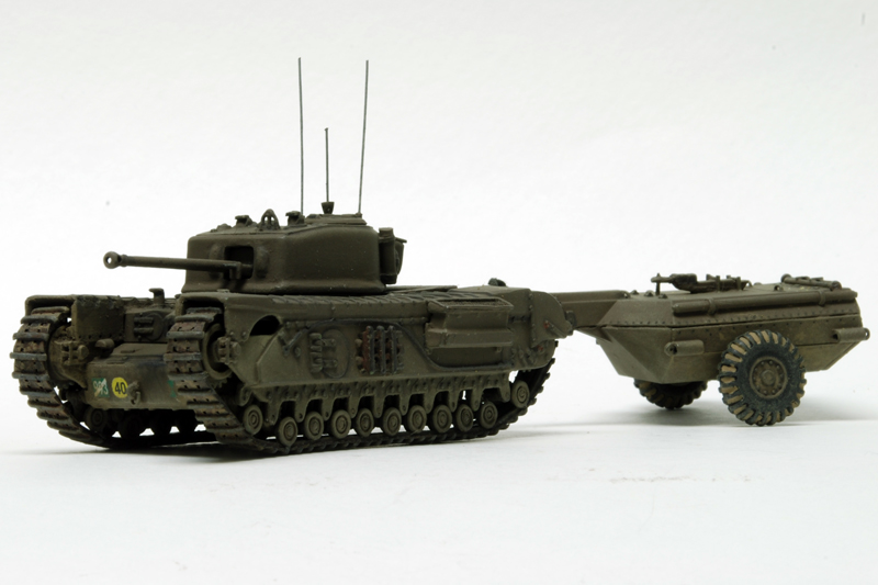
Now to the Crocodile trailer:

George Bradford’s drawings and the few wartime photos I found, show a much more complicated trailer than the museum one which Airfix presumably copied. Perhaps a later model? However, I wanted to try and match the wartime photos. I added bolted plates either side of the main center rear opening, made from sheet and rod. The center opening was missing the bar assembly that held it closed so I made it from sheet and brass wire. I added three handles to the rear hatches from brass wire. On the right hand side is the plate for attaching a telescoping leg to keep the trailer horizontal when not attached to the Churchill. This was made from thin sheet with an inverted u-shape on top. The second plate, for the second leg was added on the same side, at the front. Wartime photos of the (unditching?) tubes on each corner show rounded ends, rather than pointed and I drilled holes through the rounded parts and indentations into the tubes to be painted black later. This picture also shows the poor fit of the rear plate that I had to fill with putty. Not sure if it was my mistake or not…

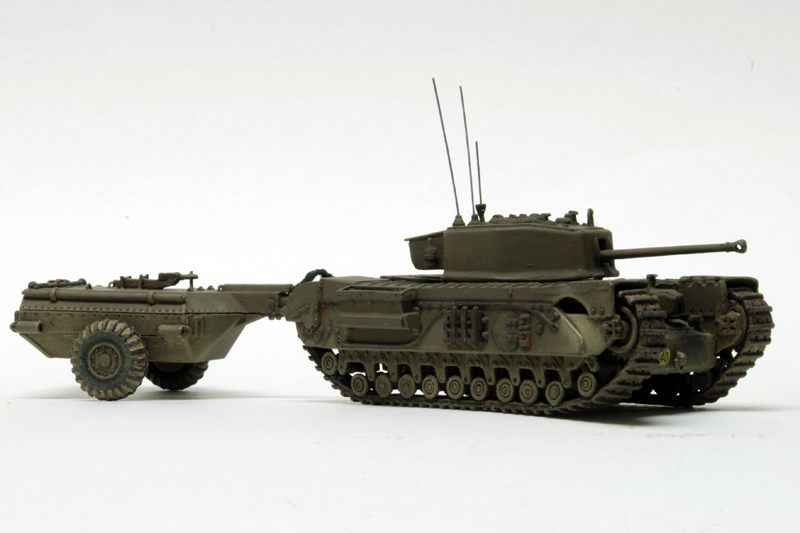
Is it me, or are the assembly instructions for the coupling wrong? I assembled the coupling three different ways before finally settling on the way shown above. Since the overall kit coupling design is not identical to the real one, I suppose it does not really matter as long as it works. The instructions have the rounded edges of the horizontal joint (allowing vertical movement) facing towards the tank, but the assembly works better the other way round, and the mating part that hooks on the tank seems to have a notch designed to accept the horizontal joint side piece. Difficult to describe and will only make sense if you have tried it.

On the trailer top, I added the two telescoping legs at the back and scribed small notches on the ends nearest the feet. I scribed the missing top rear hatch edges and added two handles. Another brass wire handle was added to the forward hatch. Annoyingly, the supplied alternate towing bar for towing the trailer behind a truck (lorry…), which was stowed on top, is too long and the wrong shape. If mounted as supplied, the front hatch would not open to access the release valves! I cut it back to the correct length at the rear undercut, carved a small step at the back and removed the bottom mounting feature so as to mount it further back on the trailer. The two mounting brackets were added from rod, again filed flat after attaching. I also added the mounting post that the towing eye fitted over, just behind the forward hatch.

The very last pieces added were for the quick disconnect cable. I added the block with undercut from thick sheet and used string (too thick) for the cable. Not ideal, but the best I had to hand. It needs to be very flexible and long enough to allow the trailer move freely.